Nuclear magnetic resonance fringe magnetic field imaging experimental device

A nuclear magnetic resonance and edge technology, applied in the direction of using nuclear magnetic resonance image system for measurement, magnetic resonance measurement, and magnetic variable measurement, can solve the problem of high-precision and high-resolution imaging that is not applicable to small samples, and high-precision and high-resolution imaging that is not applicable Imaging, adjustment errors and other issues, to avoid fatigue operation or misoperation, accurate experimental results, precise displacement effect

Inactive Publication Date: 2015-10-21
XIAMEN UNIV
View PDF8 Cites 0 Cited by
  • Summary
  • Abstract
  • Description
  • Claims
  • Application Information

AI Technical Summary

Problems solved by technology

In the international arena, there are no publicly available examples of related patents on the experimental equipment of nuclear magnetic resonance fringe magnetic field imaging technology; in terms of international research papers, the experimental devices involved in nuclear magnetic resonance fringe magnetic field imaging technology have their own characteristics: M. Ciffelli (Cifelli M.A practical tutorial to set up NMR diffusionometry equipment: application to liquid crystals [J]. Magn. Reson. Chem, 2014, 52(10): 640-648.) described a method in existing NMR equipment Under certain conditions, it is extremely simple to manually improve the method of NMR fringe magnetic field imaging, which has achieved the expected effect, but there will always be some errors in

Method used


Image

  • Nuclear magnetic resonance fringe magnetic field imaging experimental device
  • Nuclear magnetic resonance fringe magnetic field imaging experimental device
  • Nuclear magnetic resonance fringe magnetic field imaging experimental device

Examples


Embodiment Construction

[0018] The present invention will be described in detail below in conjunction with the accompanying drawings.

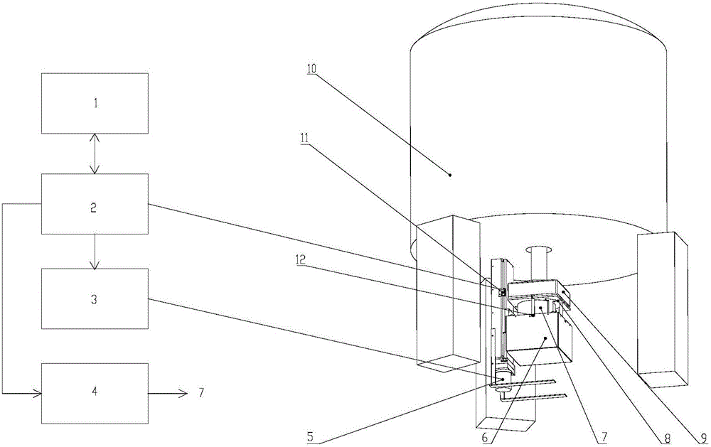
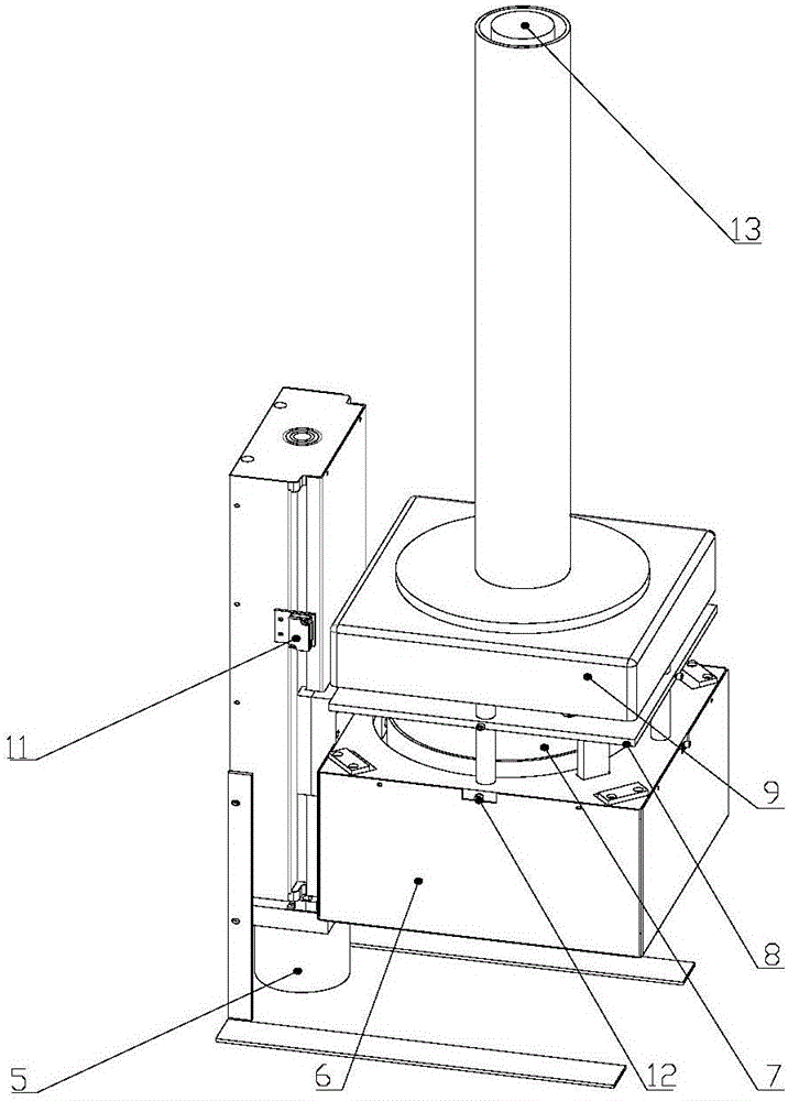
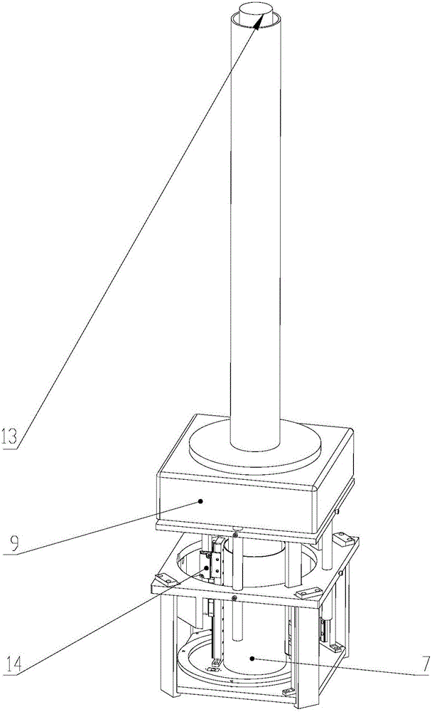
[0019] Such as Figure 1~3 As shown, the embodiment of the present invention is provided with a host computer 1 integrating an advanced closed-loop control algorithm, a PMAC controller 2, a servo motor driver 3, a voice coil motor driver 4, a servo motor 5, a coarse adjustment non-magnetic lifting platform 6, and a voice coil motor 7. Fine adjustment non-magnetic lifting table 8. NMR edge magnetic field imaging high-resolution probe with humidity sensor and temperature sensor 9. Magnet 10. Coarse adjustment non-magnetic lifting table grating scale 11. Relative movement / stationary between probe coil and sample Conversion pin 12, sample cavity 13, fine-tuning non-magnetic lifting table grating scale 14.

[0020]The nuclear magnetic resonance edge magnetic field imaging probe 9 has a humidity sensor and a temperature sensor, and the host computer 1 integrates an advanc...


PUM


Abstract

A nuclear magnetic resonance (NMR) fringe magnetic field imaging experimental device relates to NMR imaging. The device comprises a servo motor, a voice coil motor, a coarse adjustment non-magnetic lifting platform, a fine adjustment non-magnetic lifting platform, a NMR fringe magnetic field imaging probe, a sample chamber, a probe coil and sample relative-mobile/static conversion pin, a coarse adjustment and fine adjustment non-magnetic lifting platform grating ruler, and a control system. The control system is composed of a principal computer, a PMAC controller, a servo motor driver, and a voice coil motor controller. A coarse adjustment and fine adjustment two-stage lifting high-precision mechanical structure and an advanced closed-loop control algorithm are combined to realize high-precision sample movement with the highest precision of 1micron and complete high-precision and high-resolution NMR fringe magnetic field imaging. Two experimental methods, namely, probe coil and sample relative-mobile imaging and probe coil and sample relative-static imaging, can be completed on one experimental device without the need for any secondary transformation, and that a strong magnetic environment is not affected is guaranteed to the maximum. Closed-loop control makes sample displacement more precise and the result more accurate.

Description

technical field [0001] The invention relates to nuclear magnetic resonance imaging, in particular to a nuclear magnetic resonance edge magnetic field imaging experimental device. Background technique [0002] Traditional nuclear magnetic resonance imaging technology has developed quite maturely today, but whether traditional nuclear magnetic resonance imaging technology is used in medicine or other fields, most of it is aimed at imaging liquid samples. Including the current research in the academic field, a large part of it is still based on liquid MRI. However, due to the strong coupling between spins and the wide resonance spectrum of solid samples, other fine spectral line structures are covered up, the transverse relaxation time is extremely short, and the signal is not easy to collect. Therefore, compared with liquid imaging, solid imaging is more convenient. Difficult. [0003] Although solid-state magnetic resonance imaging started late in the international research...

Claims


Application Information

Patent Timeline
IPC IPC(8): G01R33/48A61B5/055
Inventor 冯吴俊薛文东洪永强施建龙
Owner XIAMEN UNIV
Why Eureka
Try Eureka