Smart skin antenna oriented strain sensor layout method

An intelligent skin antenna and strain sensor technology, which is applied in the fields of instruments, special data processing applications, electrical digital data processing, etc., can solve the problems of randomness, large uncertainty, low measurement accuracy, and coordination and consideration of other factors.

Active Publication Date: 2015-10-21
XIDIAN UNIV
View PDF5 Cites 19 Cited by
  • Summary
  • Abstract
  • Description
  • Claims
  • Application Information

AI Technical Summary

Problems solved by technology

[0009] 1. The number of sensors is mostly considered and determined based on factors such as experience and economics. It is random and uncertain, and most of the optimal layout is discussed under the condition of a given number of sensors.
[0010] 2. The existing sensor optimization layout method is mainly used in the safety detection of some important structures, such as bridges, hangars, etc., and there is little research on the deformation measurement applied to antenna structures
And the layout method only

Method used


Image

  • Smart skin antenna oriented strain sensor layout method
  • Smart skin antenna oriented strain sensor layout method
  • Smart skin antenna oriented strain sensor layout method

Examples


Embodiment Construction

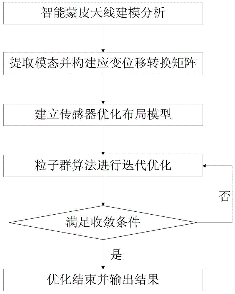
[0068] The layout method of the strain sensor facing the smart skin antenna of the present invention is realized based on the topology optimization method, and can optimize the position and number of the sensors at the same time.
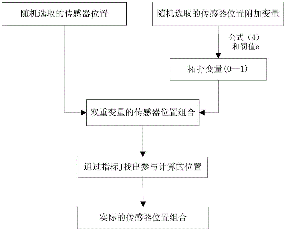
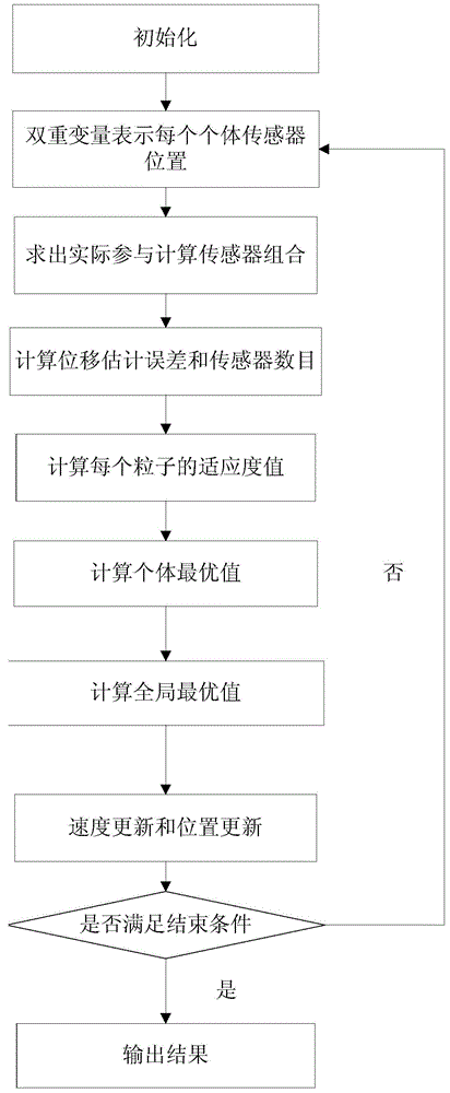
[0069] The overall idea of ​​the present invention is: take the sensor position and total number as design variables, the linear weighted sum of displacement estimation error (RMS) and the total number of sensors as the objective function, give the upper bound of the total number of sensors, and add 0-1 topology to each position variable Variables, double variables are used to represent the combination of sensor positions, an optimization model is established, and the sensor position and total number are optimized at the same time.

[0070] The following describes the present invention in detail with reference to the drawings and specific embodiments.

[0071] Reference figure 1 , The layout method of the strain sensor of the present invention includes th...


PUM


Abstract

The present invention discloses a smart skin antenna oriented strain sensor layout method. The whole idea of the method is that with positions and the total number of sensors as design variables and with the linear weighted sum of the displacement estimation errors and the total number of sensors as a target function, providing an upper limit of the total number of the sensors; adding an 0-1 topology variable to each position variable; representing a sensor position combination with dual variables; establishing an optimization model; and optimizing positions and the total number of the sensors. The smart skin antenna oriented strain sensor layout method is beneficial in that the number and positions of sensors can be both optimized effectively.

Description

Technical field [0001] The invention relates to a strain sensor layout method, in particular to a strain sensor layout method oriented to an intelligent skin antenna, and belongs to the technical field of sensor optimized layout. Background technique [0002] Smart skin antenna refers to embedding the radio frequency components and sensor elements of the integrated antenna array into airborne, shipborne, spaceborne and vehicle-mounted structures. In service, due to the influence of aerodynamics, vibration, shock or temperature load, the structure of the smart skin antenna will be deformed. The sensor system is the eye of the entire smart skin antenna system, through which the antenna can be used to obtain and transmit information while adapting to various harsh environments. Due to the limitation of test conditions, it is necessary to embed strain sensors in the skin antenna to obtain comprehensive and accurate test information and measure its deformation in real time. The pate...

Claims


Application Information

Patent Timeline
IPC IPC(8): G06F17/50
Inventor 李海洋周金柱杜敬利段宝岩李明
Owner XIDIAN UNIV
Why Eureka
Try Eureka