An Atmospheric Pressure Microwave Plasma Excitation Source Device and Its Application

A technology of microwave plasma and excitation source, which is applied in the field of chemical measurement, can solve the problems of prolonging sample analysis time, requirement of sample shape, insufficient ionization ability, etc., and achieve the effects of not easy quenching, strong sample tolerance, and reduced interference

Inactive Publication Date: 2017-10-31
ZHEJIANG UNIV
View PDF5 Cites 0 Cited by
  • Summary
  • Abstract
  • Description
  • Claims
  • Application Information

AI Technical Summary

Problems solved by technology

However, the existing atmospheric desorption ionization source has the defects of insufficient ionization ability, limited ionization range, and requirements for the shape of the sample, which are not enough to meet people's requirements, and often require pretreatment of the sample before analyzing the sample. It will prolong the time of sample analysis, and the introduction of pretreatment reagents will interfere and affect the subsequent analysis

Method used


Image

  • An Atmospheric Pressure Microwave Plasma Excitation Source Device and Its Application
  • An Atmospheric Pressure Microwave Plasma Excitation Source Device and Its Application
  • An Atmospheric Pressure Microwave Plasma Excitation Source Device and Its Application

Examples


Embodiment 1

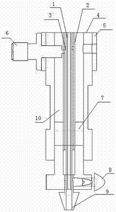
[0035] see figure 1 , an atmospheric pressure microwave plasma excitation source device consists of an inner tube 1, a middle tube 2, a calibration pad 3, an outer tube 4, a microwave feed-in interface 5, a coaxial cable SMA connector 6, a tuning piston 7, and a side gas inlet port 8, the lower end gas inlet port 9, composed of coaxial channel 10.

[0036] The middle tube 2 is located between the inner tube 1 and the outer tube 4, the calibration pad 3 is fixed between the inner tube 1 and the middle tube 2, and the coaxial cable SMA connector 6 is fixed on the microwave feed-in interface by screws (not shown in the figure) 5, the inner hole of the microwave feed-in interface 5 is tightly fitted with the outer tube 4, and the bolt is fastened to the fixing screw hole 14 of the microwave feed-in interface of the outer tube through the microwave feed-in interface fixing hole 20 on the microwave feed-in interface 5. The axial cable SMA connector 6 passes through the outer tube 4...

Embodiment 2

[0049] Embodiment 2 Working process of the present invention

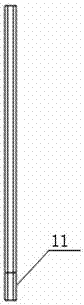
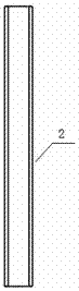
[0050] Open the gas flow meter, the gas inlet hose is fixed on the gas introduction pipe joint 33, the middle pipe 2 is fixed on the middle pipe fixing interface 30 through its bottom thread, and the inner pipe 1 is fixed on the lower end gas introduction port 9 through the threaded end surface 11 On the fixed thread 32 of the inner inner tube, a calibration pad 3 is added between the inner tube 1 and the middle tube 2 to compensate for mechanical assembly errors, and at the same time, the gas in the middle tube 2 enters the reaction area through the exhaust hole 12 . Control the gas flow in the middle tube 2 and the inner tube 1, and select the appropriate helium (or argon) flow rate. Turn on the microwave source to generate 5.8Ghz microwave energy, and connect the output port of the microwave source to the microwave coaxial connection screw port 23 on the SMA connector 6 of the coaxial cable through a 50Ω coaxial...


PUM


Abstract

The invention provides a microwave plasma excitation source at atmospheric pressure, including an inner tube, a middle tube, an outer tube, a calibration pad, a microwave feed-in interface, a coaxial cable SMA connector, a tuning piston, a side-end gas introduction port, and a lower-end gas introduction port and coaxial channels. The invention has a three-tube coaxial structure to form a plasma with a central channel, which can not only work stably under high-power microwave conditions, but also be excited and used under low-power conditions; stable He plasma can be obtained under normal pressure, with Strong excitation ability and wide measurement range; it can reduce background emission and interference; diversification of ionization modes: it can not only introduce samples into the inner tube for analysis, but also directly monitor the surface of samples in real time. The invention has reasonable design, simple structure, simple operation and wide application, can be used for mass spectrometer ion source, spectrometer excitation source, etc., does not need sample pretreatment, has strong sample bearing capacity and wide measurement range.

Description

technical field [0001] The invention belongs to the technical field of chemical measurement, and relates to an atmospheric pressure microwave plasma excitation source device, which relates to a device using 5.8Ghz (other frequency microwave sources can also be used) microwave atmospheric pressure excitation plasma. Background technique [0002] Direct ionization technology represented by atmospheric pressure desorption ionization source is a revolutionary development in the field of mass spectrometry in recent years, and its importance to work and scientific research is immeasurable. However, the existing atmospheric desorption ionization source has the defects of insufficient ionization ability, limited ionization range, and requirements for the shape of the sample, which are not enough to meet people's requirements, and often require pretreatment of the sample before analyzing the sample. It will prolong the time of sample analysis, and the introduced pretreatment reagent ...

Claims


Application Information

Patent Timeline
Patent Type & Authority Patents(China)
IPC IPC(8): H05H1/46
Inventor 周建光赵高升于东冬龚晨陈怡萍高颖郑天宇
Owner ZHEJIANG UNIV
Why Eureka
Try Eureka