Electrode catalyst, method for preparing same, and membrane electrode assembly and fuel cell comprising same

A technology of electrode catalyst and membrane electrode assembly, which is applied in the direction of fuel cells, fuel cell parts, electrical components, etc., can solve the problems of poor oxygen diffusion and mechanical stiffness of the catalytic layer, so as to promote flow and improve electrical components. performance effect

Inactive Publication Date: 2015-10-21
GLOBAL FRONTIER CENT FOR MULTISCALE ENERGY SYST +1
View PDF3 Cites 3 Cited by
  • Summary
  • Abstract
  • Description
  • Claims
  • Application Information

AI Technical Summary

Problems solved by technology

In this way, the drainage volume can be effectively increased through the catalytic layer, but as the porosity increases, the thickness of the catalytic layer will also increase, making the diffusion of oxygen worse, and causing the mechanical stiffness of the catalytic layer to deteriorate

Method used


Image

  • Electrode catalyst, method for preparing same, and membrane electrode assembly and fuel cell comprising same
  • Electrode catalyst, method for preparing same, and membrane electrode assembly and fuel cell comprising same
  • Electrode catalyst, method for preparing same, and membrane electrode assembly and fuel cell comprising same

Examples


example 1

[0087] Example 1: Synthesis of Pt / C-PNIPAM

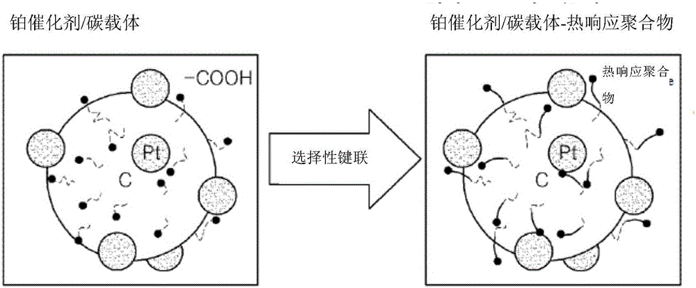
[0088] Disperse Pt / C (40wt%, Johnson Matthey) together with PNIPAM (Aldrich) terminal amino group represented by structural formula 4 in an acid solution with a pH value of 1.6. The acid solution was composed of 300 mL of isopropanol (IPA, Aldrich) and 0.6 mL of HClO 4 (Aldrich) composition. After the solution was stirred and mixed for 1 h, 1-ethyl-3-carbodiimide (3-dimethylaminopropyl) (EDC, Fluka) was added as a catalyst to the stirred solution to initiate -COOH and PNIPAM terminals on the carbon surface The -NH2 of the amino group undergoes an amide reaction. After 12 hours of EDC-induced amide reaction, the solution was filtered and washed with excess deionized (DI) water. The filtered Pt / C-PNIPAM was dried at 60 °C, and finally, the Pt / C-PNIPAM powder was deposited in a mortar.

[0089] General structural formula 4 is:

[0090]

[0091] where the value of n is 25.

example 2

[0092] Example 2: Membrane Electrode Assembly (MEA) Preparation

[0093] In this example, a membrane electrode assembly was prepared whose cathode contained PNIPAM.

[0094] The catalyst slurry for the cathode catalytic layer containing PNIPAM was prepared by mixing 6.3 mg of Pt / C-PNIPAM, Nafion ionomer solution (Aldrich) (N / C ratio 0.5) and IPA (0.63 mL). A pretreated Nafion212 membrane (DuPont) was used. The catalyst slurry was boiled in 3% hydrogen peroxide solution and rinsed in deionized water. Then, the catalyst slurry was soaked in 0.5 M H 2 SO 4 and rinse again with deionized water. Each step in the solution was treated at 80°C for 1 hour. Spray the prepared catalyst slurry onto the anode and cathode parts of the Nafion212 membrane.

[0095] The catalyst-coated membranes were dried at room temperature for 12 h and sandwiched between the anode and cathode gas diffusion layers (SGL35BC) without autoclaving. The active geometric area of ​​the MEA is 5cm 2 . Compa...

experiment example 1

[0099] For the unit cells prepared in Example 2 and Comparative Example 1, each catalytic surface was analyzed by x-ray photoelectron spectroscopy (XPS). The result is as Figure 5 shown.

[0100] from Figure 5 In the shown results, it can be known that the Pt / C-PNIPAM contained in the catalytic layer of Example 2 has an N1s peak at 400.5eV, indicating that PNIPAM is indeed located on the Pt / C, and forms between the carbon surface and the PNIPAM amide bond. Furthermore, this establishes that PNIPAM binds selectively only to carbon surfaces and has no effect on Pt surfaces.


PUM

PropertyMeasurementUnit
diameteraaaaaaaaaa
diameteraaaaaaaaaa
diameteraaaaaaaaaa

Abstract

The present invention relates to an electrode catalyst, a method for preparing the electrode catalyst, and a membrane electrode assembly and a fuel cell including the electrode catalyst. The electrode catalyst includes a carbon support and a platinum catalyst supported on the carbon support. A thermally responsive polymer is selectively bound to the carbon support. The electrode catalyst can ensure smooth discharge of water produced as a result of an electrochemical reaction, achieving improved electrical performance of the fuel cell.

Description

technical field [0001] The invention relates to an electrode catalyst, which can ensure the smooth discharge of water produced by electrochemical reaction, and also relates to a manufacturing method of the electrode catalyst, a membrane electrode assembly and a fuel cell with the membrane electrode assembly. Background technique [0002] Fuel cells have always been regarded as a popular alternative energy source. Fuel cells can be divided into polymer electrolyte membrane fuel cells (PEMFC), direct methanol fuel cells (DMFC), phosphoric acid fuel cells (PAFC), molten carbonate fuel cells (MCFC) and solid oxide fuel cells according to the electrolyte and fuel used. fuel cells (SOFCs). [0003] In a hydrogen fuel cell (such as a polymer electrolyte membrane fuel cell), the hydrogen injected into the positive electrode reacts electrochemically with the oxygen injected into the anode to generate direct current, water, and heat. At the same time, water generated by the cathode ...

Claims


Application Information

Patent Timeline
Patent Type & Authority Applications(China)
IPC IPC(8): H01M4/90H01M4/86H01M8/02
CPCH01M4/9008H01M4/86H01M4/8878H01M4/90H01M4/9083H01M4/926H01M8/02H01M8/1004H01M2008/1095H01M2300/0082H01M4/8663H01M8/04156Y02E60/50
Inventor 金相彣郑南杞徐甲亮成永恩崔万秀
Owner GLOBAL FRONTIER CENT FOR MULTISCALE ENERGY SYST
Why Eureka
Try Eureka