Portable track vacuum control system

A technology of vacuum control and control system, applied in the field of vacuum system, can solve the problems of a large number of manpower and material resources, the influence of energy consumption and life of vacuum pump, and the decline of work efficiency.

Active Publication Date: 2015-10-28
大连四达高技术发展有限公司
View PDF6 Cites 0 Cited by
  • Summary
  • Abstract
  • Description
  • Claims
  • Application Information

AI Technical Summary

Problems solved by technology

[0003] The vacuum system is generally composed of a vacuum pump, a suction cup and a connecting pipeline. When working, the vacuum pump is turned on, and the suction cup absorbs the portable track to install the track. During the working process of the equipment, the vacuum pump needs to work continuously, and the energy consumption of the vacuum pump It has a great impact on the service life, and once a leak is found in the pipeline, you can only stop working and check the leak point, which often wastes a lot of time and energy, resulting in a decline in work efficiency
And when a vacuum system controls the adsorption of multiple sets of tracks at the same time, the installation process of the tracks has very strict requirements on the vacuum degree of the entire vacuum system. Only these multiple sets of tracks can be installed at the same time, requiring a lot of manpower and material resources

Method used


Image

  • Portable track vacuum control system

Examples


Embodiment Construction

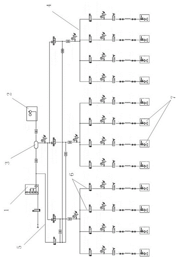
[0009] The specific implementation manner of the present invention will be described below with reference to the accompanying drawings. Such as figure 1 Shown: a portable track vacuum control system, which includes a multi-stage vacuum generator 1 and a vacuum pump 2, the multi-stage vacuum generator 1 and the vacuum pump 2 are all connected to the vacuum tank 3, and the vacuum tank 3 is directly connected to the vacuum tank through the main pipeline Multiple sets of track vacuum management units 4 are connected, and valves and pressure gauges are set between the vacuum tank 3 and each set of track vacuum management units 4; branch pipes are connected to the pipeline between the multi-stage vacuum generator 1 and the vacuum tank 3 Road 5, this branch line 5 is also connected to all track vacuum management units 4 respectively, and valves are also arranged on the branch line 5; the track vacuum management unit 4 includes four parallel branch lines 6, each branch Suction cups 7...


PUM


Abstract

The invention discloses a portable track vacuum control system. The portable track vacuum control system is characterized in that the control system comprises a multi-stage vacuum generator (1) and a vacuum pump (2), and the multi-stage vacuum generator (1) and the vacuum pump (2) are connected with a vacuum tank (3); the vacuum tank (3) is connected with a plurality of sets of track vacuum management units (4) through a main pipeline, and a valve and a pressure gauge are arranged between the vacuum tank (3) and each track vacuum management unit (4); a branch pipeline (5) is connected to the pipeline between the multi-stage vacuum generator (1) and the vacuum tank (3) and connected with all the track vacuum management units (4), and a valve is also arranged on the branch pipeline (5); each track vacuum management unit (4) comprises four sub-pipelines (6) connected in parallel; and a suction cup (7) is arranged at the tail end of each sub-pipeline (6), and an electric valve, a pressure gauge and a manual valve are arranged on each sub-pipeline (6).

Description

technical field [0001] The invention relates to a vacuum system, in particular to a portable track vacuum control system. Background technique [0002] With the development of science and technology, people have higher and higher requirements for equipment that uses rail guidance for mobile operations. In the past, these equipment could only work on fixed stations through rails. If you want to use these equipment for new working places, then Installing new tracks, or dismantling existing tracks for reinstallation, either way adds significantly to cost. In order to solve this problem, relevant designers have invented portable tracks. Because the installation and disassembly of this portable track is relatively convenient and simple, the flexibility of equipment operation has been greatly improved. Portable track is a relatively common installation method when it is vacuum adsorbed and fixed. This method has high requirements for the vacuum system during installation and use...

Claims


Application Information

Patent Timeline
IPC IPC(8): B65G53/66
Inventor 李东栓
Owner 大连四达高技术发展有限公司
Why Eureka
Try Eureka