Drill rod distribution structure of cement soil mixing pile driver

A technology of cement-soil mixing piles and pile drivers, which is applied in the direction of earth drilling, foundation structure engineering, sheet pile walls, etc., can solve the problems of cement-soil mixing piles such as poor pull-out resistance, uneven mixing, and low construction efficiency, and achieve The drilling difficulty is small, the mixing is uniform, and the effect of saving construction cost

Active Publication Date: 2015-10-28
周兆弟
View PDF4 Cites 9 Cited by
  • Summary
  • Abstract
  • Description
  • Claims
  • Application Information

AI Technical Summary

Problems solved by technology

The above scheme solves the problem of low construction efficiency of the existing cement-soil mixing pile machine to a certain extent, but the scheme still exists: the mixing is not uniform enough, the cement-soil mixing pile has poor pull-out resistance, drilling is difficult, and the problems of poor stability

Method used


Image

  • Drill rod distribution structure of cement soil mixing pile driver
  • Drill rod distribution structure of cement soil mixing pile driver
  • Drill rod distribution structure of cement soil mixing pile driver

Examples


Embodiment 1

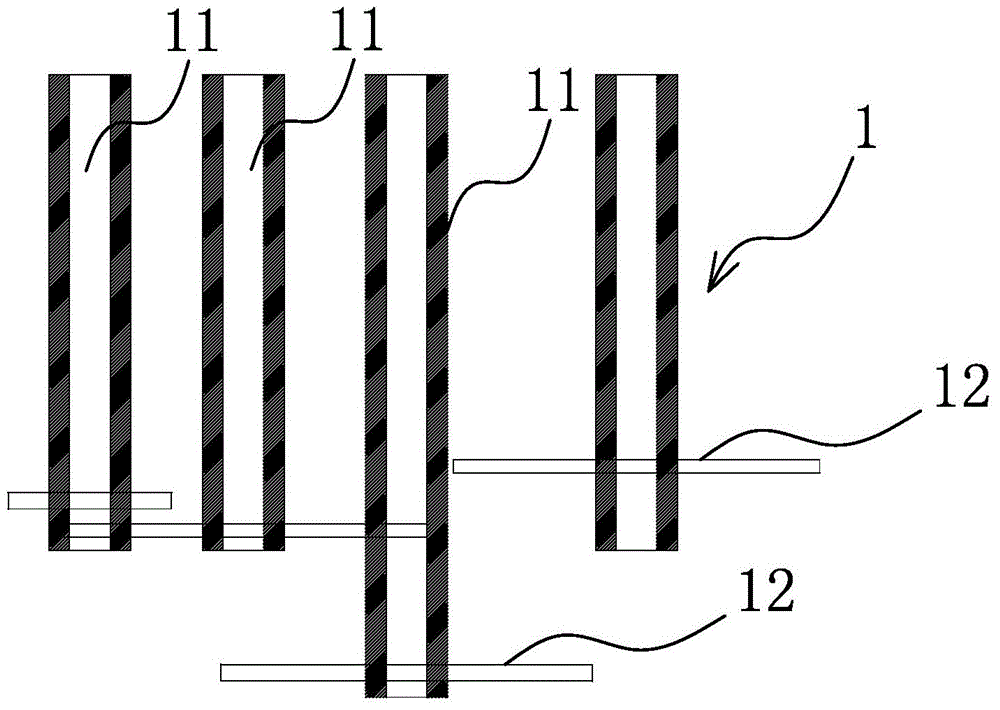
[0026] like Figure 1-2 As shown, the drill pipe distribution structure of the cement-soil mixing pile driver includes a drill pipe assembly 1 having at least three drill pipe bodies 11 that can rotate circumferentially and are vertically arranged, and each drill pipe body 11 is provided with a number of stirring body 12, the projection of the centerline of the drill pipe body 11 in the drill pipe assembly 1 in the vertical direction is not on the same straight line, and the projections of any three centerlines in the drill pipe assembly 1 in the vertical direction are not on the same straight line The centerlines of the drill pipe bodies 11 are connected successively to form a triangular structure, and the drill pipe bodies 11 are vertically dislocated one by one. Obviously, the drill pipe bodies 11 in each drill pipe assembly 1 are not located on the same straight line, which increases the construction time. The perimeter of the cross-section of the cement-soil mixing pile i...

Embodiment 2

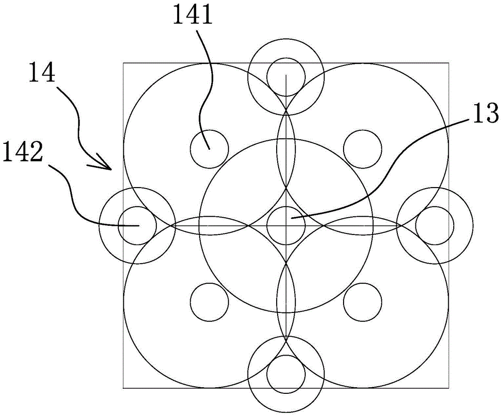
[0034] like Figure 6 As shown, the structure, principle and implementation steps of this embodiment are similar to those of Embodiment 1. The difference is that the main drill rods 13 and auxiliary drill rods 14 in this embodiment are arranged in a rectangular array. Preferably, the The quantity of main drilling rod 13 is one, and the quantity of auxiliary drilling rod 14 is eight, and because main drilling rod 13 and auxiliary drilling rod 14 are arranged in a rectangular arrangement, so that one step can drill approximately rectangular boreholes, like this The cross-sectional area of ​​the cement-soil mixing pile is increased.

Embodiment 3

[0036] like Figure 7 As shown, the structure, principle and implementation steps of this embodiment are similar to those of Embodiment 1. The difference is that the auxiliary drill pipe 14 in this embodiment is arranged in a ring shape with the main drill pipe 13 as the center of circle and evenly distributed, for example , the quantity of auxiliary drilling rod 14 here is four, and the quantity of main drilling rod 13 is one and is arranged on the center of auxiliary drilling rod 14, so that one step can get out the approximately rectangular borehole, increased cement-soil like this The cross-sectional area of ​​the mixing pile.


PUM


Abstract

The invention belongs to the technical field of construction equipment, and particularly relates to a drill rod distribution structure of a cement soil mixing pile driver. The drill rod distribution structure of the cement soil mixing pile driver solves the problem that an existing cement soil mixing pile driver is low in drilling efficiency and the like. The drill rod distribution structure of the cement soil mixing pile mixer comprises a drill rod assembly with at least three drill rod bodies which rotate in the circumferential direction and are arranged in the vertical direction; each drill rod body is provided with multiple stirring bodies; the projections of the center lines of the drill rod bodies in the drill rod assembly in the vertical direction are not located on the same straight line; the center lines of any three drill rod bodies, with the projections of the center lines in the vertical direction not located on the same straight line, of the drill rod assembly are sequentially connected to form a triangular structure; the drill rod bodies are arranged in the vertical direction in a one-to-one staggered mode. The drill rod distribution structure of the cement soil mixing pile driver has the advantages that stirring is uniform; a manufactured cement soil mixing pile is high in anti-pulling capacity; the drilling difficulty is low; drill holes in an approximate rectangle can be drilled at a time; machine movement or repeated drilling is not needed; the construction cost is saved; stability is good.

Description

technical field [0001] The invention belongs to the technical field of construction equipment, and in particular relates to a drill rod distribution structure of a cement-soil mixing pile driver. Background technique [0002] The cement-soil mixing pile is a method for reinforcing the low foundation of saturated soft clay. It uses cement as the curing agent, and through a special mixing machine, the soft soil and the curing agent are forced to mix deep in the foundation. A series of physical and chemical reactions between them make the soft soil harden into a high-quality foundation with integrity, water stability and certain strength. Common pile drivers for cement-soil mixing piles are mostly two-axis mixing piles, which are formed by the intersection of two equal-diameter cylinders. For two-axis cement-soil mixing piles, in order to improve the water-stop effect, it is necessary to construct around the foundation pit Two rows of cement-soil mixing piles, after the first ...

Claims


Application Information

Patent Timeline
Patent Type & Authority Applications(China)
IPC IPC(8): E02D5/46E21B4/16
CPCE02D5/46
Inventor 周兆弟
Owner 周兆弟
Why Eureka
Try Eureka