Floor mining damage zone multi-section blocking synchronous leakage detection method

A technology for floor mining and damage zones, which is applied in the directions of surveying, earthwork drilling, sealing/packing, etc., which can solve the problems of small number of survey sections, heavy workload, and large blindness, so as to achieve reduced workload and fewer times of movement , the effect of long total length

Active Publication Date: 2015-10-28
SHANDONG UNIV OF SCI & TECH
View PDF10 Cites 16 Cited by
  • Summary
  • Abstract
  • Description
  • Claims
  • Application Information

AI Technical Summary

Problems solved by technology

[0003] However, due to the complex site conditions, to a certain extent, the numerical simulation cannot reflect the site conditions well, and the blindness of the empirical formula is relatively large. As the mining depth increases, the applicability of the empirical formula becomes worse and worse.
When measuring in the field measurement, only one section can be measured each time, the measurement length of each section is about 1.5m, and the length of the drilling hole is about 30-50m, which causes the measuring equipment to move too many times in the drilling hole, due to the inclination angle of the drilling hole. Due to the error of the water head pressure and the defects of the equipment itself, the measurement section of the original measurement method cannot be too long each time, the number of measurement sections is small (usually 1 measurement section), the workload is large, the number of times the measurement equipment moves, and the measurement is not accurate, etc. question

Method used


Image

  • Floor mining damage zone multi-section blocking synchronous leakage detection method
  • Floor mining damage zone multi-section blocking synchronous leakage detection method
  • Floor mining damage zone multi-section blocking synchronous leakage detection method

Examples


Embodiment Construction

[0048] The present invention will be described in detail below in conjunction with specific embodiments.

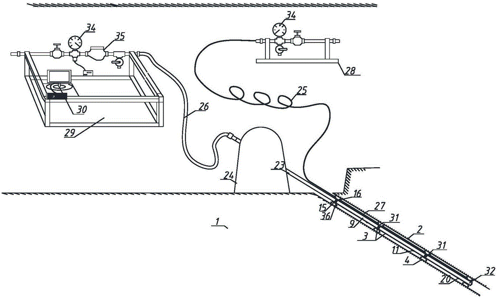
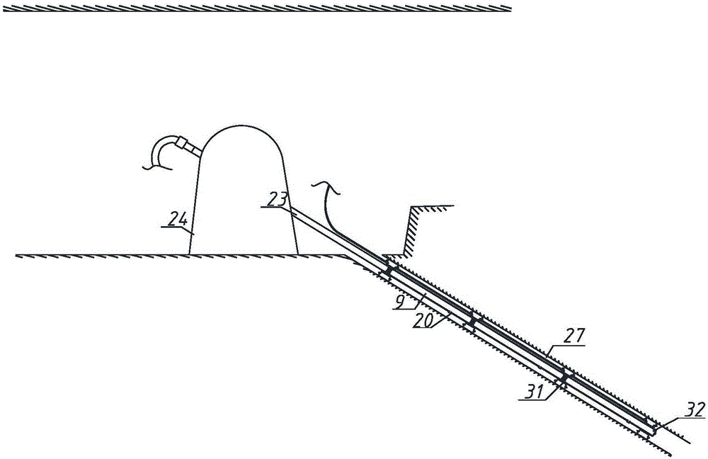
[0049] The method for synchronous leak detection with multi-stage plugging of the mining damage zone of the floor of the present invention, the leak detection system adopted is as follows: figure 1 , figure 2 As shown, it mainly includes a detection system, a plugging system and a supply measurement system. The detection system is installed in the borehole in the fracture zone, the plugging system is used to seal the borehole, and the supply measurement system is used to provide water and gas sources.

[0050] The probing system includes test probes such as image 3 As shown, the test probe is different from the prior art. It is not a whole, but is formed by connecting several detection units in sequence. The front detection unit 301, the middle detection unit 302 and the tail detection unit 303 near the outside, combined Figure 4 with Image 6 As shown, each detect...


PUM


Abstract

The invention discloses a floor mining damage zone multi-section blocking synchronous leakage detection method, which comprises the following steps of: forming a downward drill hole in a roof rock layer from a coal rock roadway, and cleaning the drill hole; installing a detection system, wherein a test probe of the detection system is formed by sequentially connecting a plurality of detection units, and the adjacent detection units are detachably connected through clamp groove joints; conveying the detection system to the initial position of the drill hole by using a drill pipe and a drilling machine in a supply measuring system; using a blocking system to seal the drill hole; using a water injection operation platform to convey a water source at the specific pressure to a water inlet pipe; processing and analyzing the collected data, then, forming a corresponding flow water vector diagram of the test section, and the like. The method provided by the invention has the advantages that the multi-section and synchronous measurement of a floor mining damage zone can be realized; the test section number in one test can be properly increased according to the length of the drill hole; the workload is exponentially reduced; and the measurement precision is improved.

Description

technical field [0001] The invention belongs to the technical field of depth measurement of mining damage zones in mines, and in particular relates to a synchronous leak detection method for multi-stage plugging of floor mining damage zones. Background technique [0002] The measurement of the depth of the mining fracture zone in the mine floor is an important parameter to indicate the occurrence state of coal and rock. It is a key basic parameter in the study of mine water prevention and control. Therefore, in order to study the formation of water-conducting channels in mining surrounding rocks, it is necessary to grasp the law of rock movement and determine the height of the mining damage zone. Numerical simulation, empirical formula prediction, field measurement and other means. [0003] However, due to the complex site conditions, to a certain extent, the numerical simulation cannot reflect the site conditions well, and the blindness of the empirical formula is relative...

Claims


Application Information

Patent Timeline
Patent Type & Authority Applications(China)
IPC IPC(8): E21B47/10E21B47/26E21B33/122
Inventor 刘伟韬宋文成赵春波刘士亮申建军张茂鹏张勤廖尚辉宰慧董文程谢祥祥穆殿瑞
Owner SHANDONG UNIV OF SCI & TECH
Why Eureka
Try Eureka