Three-mode dielectric cavity filter

A dielectric cavity and filter technology, which is applied to waveguide devices, resonators, electrical components, etc., can solve the problems of reducing filter volume and high filter loss, and achieve the effect of reducing volume and low passband loss

Inactive Publication Date: 2015-10-28
江苏吴通物联科技有限公司
View PDF13 Cites 12 Cited by
  • Summary
  • Abstract
  • Description
  • Claims
  • Application Information

AI Technical Summary

Problems solved by technology

In the existing three-mode dielectric filter, the mode with a small Q value is selected to form a mixed three-mode, so that the filter loss is relatively high; in addition, the traditional single-mode filter needs three resonant cavities to realize the mixing of the three modes. Brings disadvantages to reduce the size of the filter

Method used


Image

  • Three-mode dielectric cavity filter
  • Three-mode dielectric cavity filter
  • Three-mode dielectric cavity filter

Examples


specific Embodiment 1

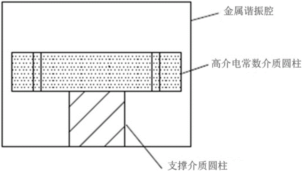
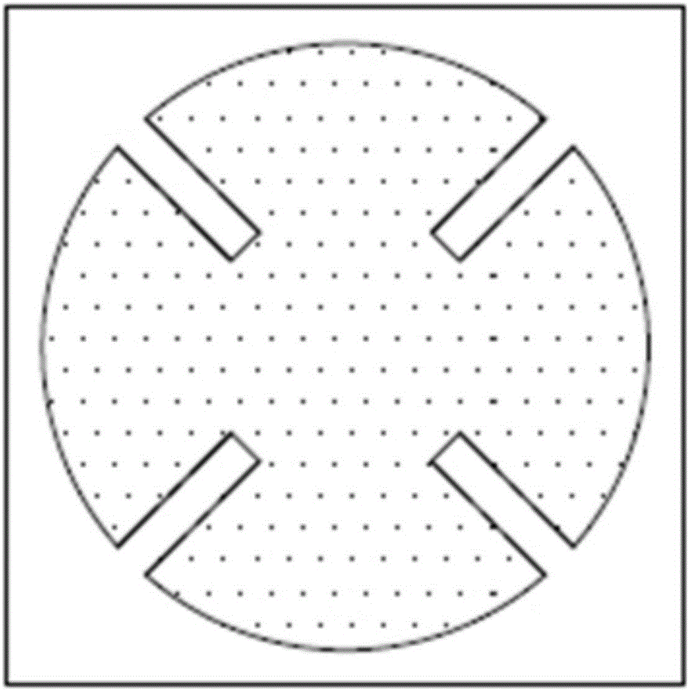
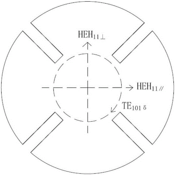
[0033] The three-mode dielectric cavity filter includes: a three-mode dielectric cavity resonator with a single-cavity structure as shown in Figure 1(a) and Figure 1(b), an input terminal, an output terminal and a coupling circuit. The three-mode dielectric cavity resonator with a single-cavity structure includes: a metal resonator, a support dielectric cylinder loaded in the center of the metal resonator, a high dielectric constant dielectric cylinder placed on the support dielectric cylinder, and a high dielectric constant dielectric cylinder at 45o , 135o, 225o, and 315o have slots in the four radial directions. The depth and length of the slots in the four directions are the same. Adjust the TE by adjusting the diameter, height, and slot length of the high dielectric constant dielectric cylinder. 01δ mode and two degenerate HEH 11 mode (HEH 11⊥ mode and HEH 11∥ mode), so that the resonant frequencies of the three modes are the same to reach the required frequency, thus r...

specific Embodiment 2

[0037] On the basis of the specific embodiment 1, screw the adjusting screws T1, T2, T3, T4 from the cover plate above the metal resonant cavity, wherein the adjusting screw T1 is used for TE 01δ Mode tuning, screw tuning T2 and screw tuning T3 are used for HEH 11∥ mode and HEH 11⊥ For tuning of the mode, set the tuning screw T4 on the diagonal of the cavity (corresponding to the position of the diagonal of the slot of the high dielectric constant dielectric cylinder), which is used in the HEH 11∥ mode and HEH 11⊥ A certain amount of coupling (cross-coupling) is introduced between the modes.

[0038] Figure 9 It is the S-parameter electromagnetic simulation curve of a one-cavity three-mode (third-order) filter (using commercial software HFSS simulation). The structure used in this filter is as described in Figure 5. The main parameters are listed as follows:

[0039] The size of the metal resonant cavity is 34*34*26mm, and the boundary of the cavity wall is set to metal...

specific Embodiment 3

[0046] Cascading a plurality of three-mode dielectric cavity filters with a single-cavity structure shown in Embodiment 1 or Embodiment 2 can realize high-order filtering. Figure 7(a) and Figure 7(b) are the structural diagrams of a two-cavity (6-order) dielectric filter, port P1 passes through the HEH of the probe and resonant cavity 1 11⊥ Mode coupling; port P2 via probe to HEH of resonator 2 11⊥ Mode coupling; the coupling structure between the three modes of resonator 1 and resonator 2 is the same as Image 6 The mode coupling structure in the resonator is the same; the HEH of resonator 1 11∥ Mode and HEH in cavity 2 11∥ The modes are capacitively coupled through metal probes to realize the cascading of resonant cavities, and the metal probes are set on the teflon dielectric probe base in the window between the two cavities. The equivalent circuit topology of a two-cavity (6th order) dielectric filter is as follows Figure 8 shown.

[0047] It should be noted that the...


PUM


Abstract

The present invention discloses a three-mode dielectric cavity filter, belonging to the technical field of a dielectric filter. The three-mode dielectric cavity filter comprises a three-mode dielectric resonator capable of realizing a TE01 delta mode and two degenerate HEH11 modes with a single resonator cavity, an input end, an output end, and a coupling circuit. The input end is coupled to one degenerate HEH11 mode through a metal probe, and the output end is coupled to the other degenerate HEH11 mode trough a metal probe. The three-mode dielectric resonator comprises a metal resonator cavity, a support dielectric cylinder which is loaded to the center of the metal resonator cavity, and a high dielectric constant dielectric cylinder placed on the support dielectric cylinder. The 45-degree, 135-degree, 225-degree and 315-degree radial directions of the high dielectric constant dielectric cylinder are provided with grooves. According to the three-mode dielectric cavity filter, the mixed resonance of TE01 delta mode and two degenerate HEH11 modes with high Q values are used in the three-mode filter, a low passband loss can be generated, the functions of traditional single-mode filter three resonator cavities are realized by using the volume of one resonator cavity, and the volume of the filter is effectively reduced.

Description

technical field [0001] The invention discloses a three-mode dielectric cavity filter and belongs to the technical field of dielectric filters. Background technique [0002] Wireless communication is developing rapidly at present. In the 4G era, a variety of standard communication standards and networks coexist, and competition with each other will be the market pattern in a long period of time. Coupled with the rapid development of various other wireless applications, including wireless local area network, navigation, bluetooth and other technologies, the current use of wireless spectrum resources is very crowded, and the mutual interference is also very serious. 4G and future 5G mobile communication base station filters and duplexers require higher out-of-band rejection, lower loss and smaller size. [0003] The dielectric cavity resonator based on high dielectric ceramic material can concentrate the field energy inside the medium and reduce the conductor loss; and becaus...

Claims


Application Information

Patent Timeline
Patent Type & Authority Applications(China)
IPC IPC(8): H01P1/207H01P1/208
CPCH01P1/2086H01P7/105
Inventor 刘云蒋帅虞春
Owner 江苏吴通物联科技有限公司
Why Eureka
Try Eureka