Double-point elastic supporting cylinder vortex induced vibration fluid kinetic energy conversion device

A technology of elastic support and vortex-induced vibration, which is applied in the direction of engines, wind power generation, engine components, etc., can solve problems such as low buoyancy efficiency, inflexible power generation methods, and narrow power generation frequency band, and achieve high support stability

Active Publication Date: 2015-10-28
HARBIN INST OF TECH
View PDF6 Cites 14 Cited by
  • Summary
  • Abstract
  • Description
  • Claims
  • Application Information

AI Technical Summary

Problems solved by technology

[0006] The present invention solves the problems of complex structure, narrow power generation frequency band, inflexible power generation mode and low buoyancy efficiency of e

Method used


Image

  • Double-point elastic supporting cylinder vortex induced vibration fluid kinetic energy conversion device
  • Double-point elastic supporting cylinder vortex induced vibration fluid kinetic energy conversion device
  • Double-point elastic supporting cylinder vortex induced vibration fluid kinetic energy conversion device

Examples


specific Embodiment approach 1

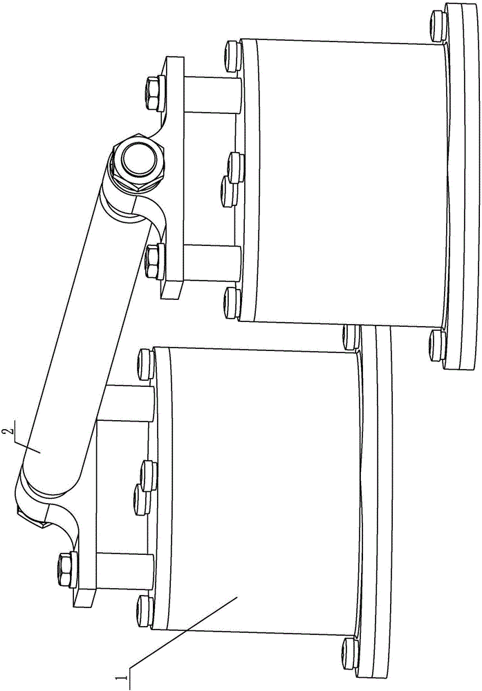
[0016] Specific implementation mode one: combine Figure 1-Figure 5 Explain that the two-point elastically supported cylindrical vortex-induced vibration fluid kinetic energy conversion device of this embodiment includes an excitation beam 2 and two exciters 1; two excitation generators 1 are arranged side by side at both ends of the excitation beam 2;

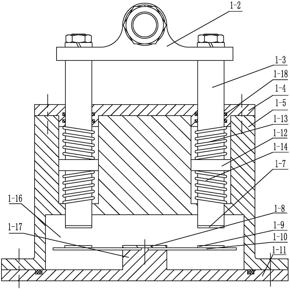
[0017] Each excitation generator 1 comprises connecting plate 1-2, sealing cover 1-4, guide column 1-5, base 1-11, two vibration columns 1-3, two excitation permanent magnets 1-7, two A vibrated permanent magnet 1-9, two cantilever beam piezoelectric buoyancy devices 1-10 and four springs; the four springs are respectively two upper springs 1-13 and two lower springs 1-14; guide column 1-1 5 is arranged on the base 1-11, a cavity 1-16 is formed between the lower end surface of the guide column 1-5 and the upper end surface of the base 1-11; 2 connections;

[0018] Two vibrating columns 1-3 are arranged side by side on the lo...

specific Embodiment approach 2

[0020] Specific implementation mode two: combination figure 2 and Figure 5 To illustrate, the raised portion 1-12 of this embodiment is an annular raised portion. With such arrangement, the structure is simple, the design is reasonable, and the operation is stable and reliable. Others are the same as in the first embodiment.

specific Embodiment approach 3

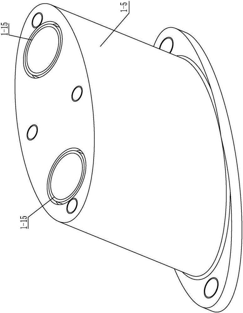
[0021] Specific implementation mode three: combination Figure 1-Figure 3 Illustrate, the cross-section of the guide post 1-5 of the present embodiment is ellipse, two through holes 1-15 are offered on the major axis of guide post 1-5, and the two cantilever beam piezoelectric buoyancy devices 1-10 The longitudinal direction of the piezoelectric sheet is parallel to the major axis direction of the guide posts 1-5. In such a setting, the excitation beam and the connecting plate are vertically arranged, and the support stability is higher. Others are the same as in the first or second embodiment.


PUM


Abstract

The invention provides a double-point elastic supporting cylinder vortex induced vibration fluid kinetic energy conversion device, relates to a fluid kinetic energy conversion device, and aims at solving problems that existing wave energy power generation devices are complex in structure, narrow in power generation frequency band, inflexible in power generation mode and low in float energy efficiency. The double-point elastic supporting cylinder vortex induced vibration fluid kinetic energy conversion device comprises a vibration excitation beam and two vibration exciters. The two vibration excitation power generators are arranged at the two ends of the vibration excitation beam in parallel. Each vibration excitation power generator comprises a connecting plate, a sealing cover, a guide column, a pedestal, two vibration columns, two vibration excitation permanent magnets, two vibrated permanent magnets, two cantilever beam piezoelectric float energy devices and four springs. The guide column is arranged on the pedestal. A cavity is formed between the lower end surface of the guide column and the upper end surface of the pedestal. The two ends of the vibration excitation beam are respectively connected with the two connecting plates. The double-point elastic supporting cylinder vortex induced vibration fluid kinetic energy conversion device is used for power generation.

Description

technical field [0001] The invention relates to a fluid kinetic energy conversion device, in particular to a fluid kinetic energy conversion device for a double-point elastically supported cylindrical vortex-induced vibration fluid kinetic energy conversion device, which belongs to the field of fluid kinetic energy new energy power generation. Background technique [0002] With the increasingly serious energy crisis, new energy technology has been paid more and more attention. On remote islands or offshore operating platforms, there are common problems of energy shortage and high transportation costs, which cause some equipment to not work normally, which brings great inconvenience to production and life. The ocean is a huge energy treasure house, and the energy contained is mainly reflected in six aspects: tidal energy, wind energy, wave energy, temperature difference energy, salt difference energy and ocean current energy. Among them, wave energy and wind energy have the c...

Claims


Application Information

Patent Timeline
IPC IPC(8): H02N2/18F03B13/00F03D9/00
CPCY02E10/72
Inventor 董帝渤陈维山王鼎汶石胜君侯珍秀
Owner HARBIN INST OF TECH
Why Eureka
Try Eureka