Photovoltaic module mounting bracket suitable for foundation sites prone to foundation settlement
A photovoltaic module and foundation settlement technology, applied in the support structure of photovoltaic modules, photovoltaic power generation, photovoltaic modules, etc., can solve the problems of photovoltaic power station operation hazards, photovoltaic module damage, photovoltaic module damage and other problems, and improve stability and durability. , the effect of reducing cracks and load impact
- Summary
- Abstract
- Description
- Claims
- Application Information
AI Technical Summary
Problems solved by technology
Method used
Image
Examples
Embodiment 1
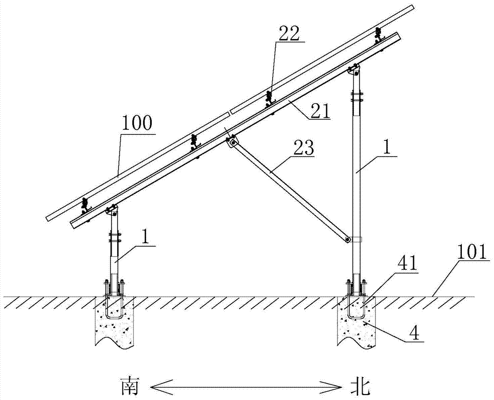
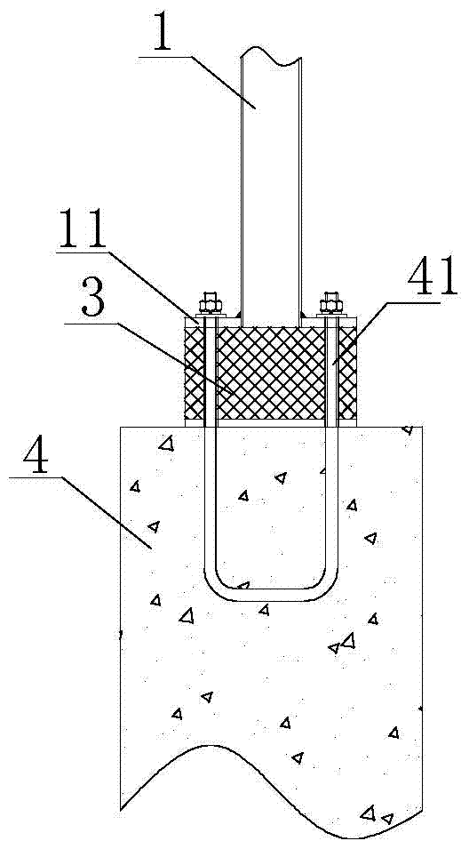
[0035] Such as Figure 1-8 As shown, the photovoltaic module installation bracket of the present invention, which is suitable for foundation sites prone to foundation settlement, is used to fix the photovoltaic module 100 on the installation surface 101. A group of beams 2 on 1, the photovoltaic module 100 is installed on the beam 2, the photovoltaic module 100 is elastically arranged on the beam 2, and the column 1 is elastically arranged on the installation surface 101. The installation surface generally refers to the site where the photovoltaic module is installed, which may be a flat surface or a slope surface, which is not limited in the present invention.
[0036] Specifically, such as Figure 1-2 As shown, the beam 2 includes a slanted beam 21 and a crossbeam 22, the slant beam 21 is connected to the column 1, the crossbeam 22 is connected to the slant beam 21, the photovoltaic module 100 is arranged on the beam 22, and an inclined beam 21 and the column 1 are also pro...
Embodiment 2
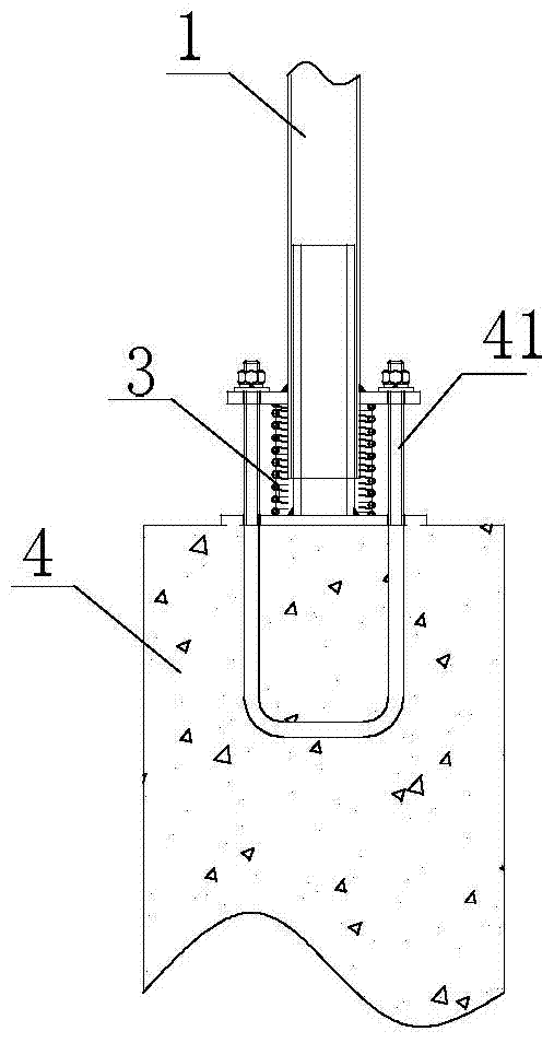
[0041] Such as Figure 8-10 The difference between the shown embodiment and Embodiment 1 is that the column 1 is connected to the installation surface 101 through the preset steel pipe pile 5, a column base 12 is provided near the bottom end of the column 1, and a steel pipe pile 5 is provided with a There is a flange plate 51, the end of the column 1 is sleeved in the steel pipe pile 5, the column base 12 and the flange plate 51 are connected by bolts, and an elastic member 3 is arranged between the column base 12 and the flange plate 51. In the embodiment, the elastic member 3 is a spring.
[0042] Figure 9 It shows a schematic structural diagram of a spring arranged between the column 1 and the steel pipe pile 5 in this embodiment, Figure 10 A schematic structural view of the column base in this embodiment is shown.
[0043] Similarly, this embodiment also uses the elastic deformation of the elastic member to absorb the partial stress generated in the support member du...
Embodiment 3
[0045] Such as Figure 11-13 As shown, this embodiment is a further improvement on the basis of Embodiment 1 and Embodiment 2, specifically: each crossbeam 22 includes a left crossbeam 22a and a right crossbeam 22b respectively, and the passage between the left crossbeam 22a and the right crossbeam 22b A connecting plate 22c is hinged, the left beam 22a and the right beam 22b are respectively provided with photovoltaic modules 100 and the junction of the left beam 22a and the right beam 22b is not provided with a photovoltaic module. Such as Figure 11 As shown, eight pile foundations (four pairs in the north and south) are selected for the unit square array in this embodiment, and the photovoltaic modules and the beams are connected by bolts, in which a support beam is divided into two sections, and the middle connection is a hinged connection, and the photovoltaic modules cannot be bridged between two paragraphs.
[0046] Divide each support beam into two sections and conn...
PUM
 Abstract
Description
Claims
Application Information
 - R&D
- Intellectual Property
- Life Sciences
- Materials
- Tech Scout
- Unparalleled Data Quality
- Higher Quality Content
- 60% Fewer Hallucinations
Browse by: Latest US Patents, China's latest patents, Technical Efficacy Thesaurus, Application Domain, Technology Topic, Popular Technical Reports.
© 2025 PatSnap. All rights reserved.Legal|Privacy policy|Modern Slavery Act Transparency Statement|Sitemap|About US| Contact US: help@patsnap.com


