Millimeter-wave orbital angular momentum communication device and method based on radio-over-optical technology
A technology of orbital angular momentum and wireless technology, which is applied in the field of millimeter-wave orbital angular momentum communication devices, can solve the problems of inability to realize high-speed signal loading, limited space of orbital angular momentum transmission channel, slow orbital angular momentum state modulation speed, etc., and achieve improved Communication capacity and spectrum utilization, long-distance transmission, and convenience
- Summary
- Abstract
- Description
- Claims
- Application Information
AI Technical Summary
Problems solved by technology
Method used
Image
Examples
Embodiment 1
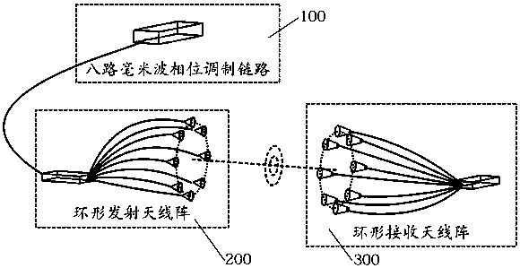
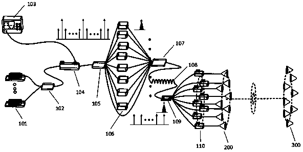
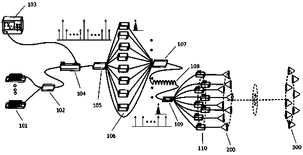
[0032] The millimeter-wave orbital angular momentum communication device based on radio-over-optical technology includes an optical millimeter-wave phase modulation link 100, a ring-shaped transmitting antenna array 200 and a ring-shaped receiving antenna array 300 connected to the optical millimeter-wave phase modulation link 100 The optical millimeter-wave phase modulation link 100 is used to modulate the orbital angular momentum phase information to the second-order upper sideband of the eight-way optical millimeter-wave signal, and generate a millimeter-wave signal after the high-speed photodetector beat frequency; the loop transmitting antenna The array 200 is used to radiate the millimeter wave signal to free space to form a vortex millimeter wave; the loop receiving antenna array 300 is used to receive the vortex millimeter wave.
[0033] Specifically, the optical millimeter wave phase modulation link 100 is an eight-way optical millimeter wave phase modulation link, whi...
Embodiment 2
[0040] The millimeter-wave orbital angular momentum communication system device based on radio-over-optical technology includes an optical millimeter-wave phase modulation link 100, an annular transmitting antenna array 200 connected to the optical millimeter-wave phase modulation link 100, and an annular receiving antenna array 300; the optical millimeter wave phase modulation link 100 is used to modulate the orbital angular momentum phase information to the high-order lower sideband of eight optical millimeter wave signals, and generate millimeter wave signals after being beat by a high-speed photodetector; the ring emission The antenna array 200 is used to radiate the millimeter wave signal to free space to form a vortex millimeter wave; the loop receiving antenna array 300 is used to receive the vortex millimeter wave.
[0041] Specifically, the optical millimeter wave phase modulation link 100 is an eight-way optical millimeter wave phase modulation link, which specificall...
Embodiment 3
[0044] The millimeter-wave orbital angular momentum communication system device based on radio-over-optical technology includes an optical millimeter-wave phase modulation link 100, an annular transmitting antenna array 200 connected to the optical millimeter-wave phase modulation link 100, and an annular receiving antenna array 300; the optical millimeter wave phase modulation link 100 is used to modulate the phase information of the orbital angular momentum to the high-order upper sideband of the eight-way optical millimeter wave signal, and generate the millimeter wave signal after the high-speed photodetector beat frequency; the ring emission The antenna array 200 is used to radiate the millimeter wave signal to free space to form a vortex millimeter wave; the loop receiving antenna array 300 receives the vortex millimeter wave.
[0045] Specifically, the optical millimeter wave phase modulation link 100 is an eight-way optical millimeter wave phase modulation link, which s...
PUM
 Abstract
Description
Claims
Application Information
 - R&D
- Intellectual Property
- Life Sciences
- Materials
- Tech Scout
- Unparalleled Data Quality
- Higher Quality Content
- 60% Fewer Hallucinations
Browse by: Latest US Patents, China's latest patents, Technical Efficacy Thesaurus, Application Domain, Technology Topic, Popular Technical Reports.
© 2025 PatSnap. All rights reserved.Legal|Privacy policy|Modern Slavery Act Transparency Statement|Sitemap|About US| Contact US: help@patsnap.com


