
A fiber optic efpi sensor demodulation device

A demodulation device and sensor technology, which is applied in the direction of using optical devices to transmit sensing components, etc., can solve problems such as limiting the application of optical fiber EFPI sensors, and achieve the effect of meeting the demodulation requirements of large dynamic range low-frequency signals and breaking through the limitation of dynamic range

Active Publication Date: 2021-09-07
BEIJING RES INST OF TELEMETRY +1
View PDF7 Cites 0 Cited by
  • Summary
  • Abstract
  • Description
  • Claims
  • Application Information

AI Technical Summary

Problems solved by technology

Existing various demodulation methods are difficult to fully meet the above-mentioned complex environment application requirements, which limits the further application of optical fiber EFPI sensors

Method used


Image

  • A fiber optic efpi sensor demodulation device
  • A fiber optic efpi sensor demodulation device
  • A fiber optic efpi sensor demodulation device

Examples


Embodiment 1

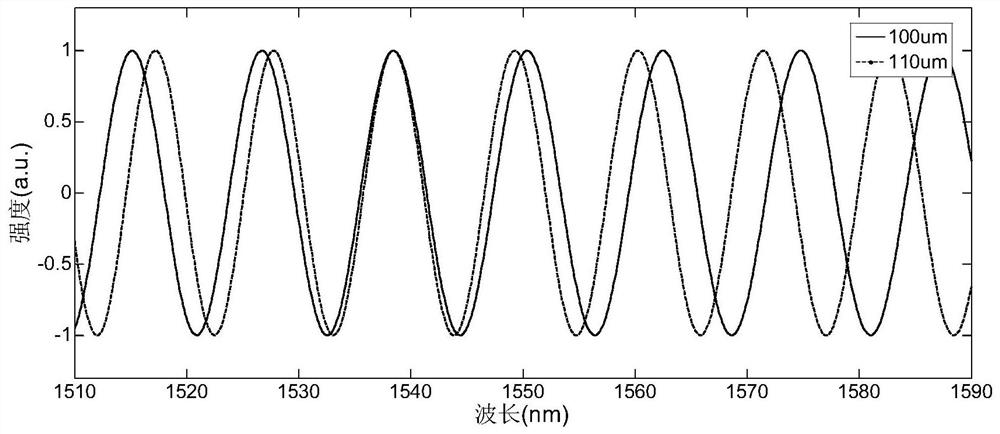
[0043] For a typical low-precision optical fiber EFPI strain sensor (the structure diagram is shown in figure 1 ) to carry out high-speed demodulation work. The low-precision optical fiber EFPI strain sensor is composed of two optical fibers, capillaries and fixed points. The end faces of the two optical fibers form the EFPI cavity. Fixed on the structure to be tested. The change of the strain of the structure leads to the change of the distance between the corresponding fixed points of the two optical fibers, and then pulls the optical fiber to move along the capillary, so that the length of the EFPI cavity changes. figure 2 The output spectra of the optical fiber EFPI strain sensor are given when the EFPI cavity length is 100um and 110um respectively. It can be seen that the output spectrum of the optical fiber EFPI strain sensor is approximately a trigonometric function, and the peak value and period vary with the length of the EFPI cavity.

[0044] This embodiment cons...

Embodiment 2

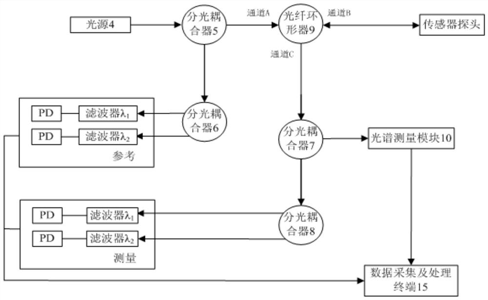
[0052] Using an independent monochromatic light source group as the intensity demodulation light source, the following Figure 6 The high-speed fiber optic EFPI sensor demodulator shown. The device consists of a broadband light source 4, a first monochromatic light source 16, a second monochromatic light source 17, a first optical splitter 5, a second optical splitter 6, an optical fiber WDM multiplexer 18, an optical fiber circulator 9, and an optical fiber WDM wave Splitter 19, volume phase grating CCD spectroscopic measurement module 10, fiber filter 20, first detector combination 13, second detector combination 14 and data acquisition and processing terminal 15. The broadband light source 4 outputs a C-band broadband optical signal (wavelength range 1530-1570nm), and the first monochromatic light source 16 and the second monochromatic light source 17 are respectively the central wavelength λ 1 =1310nm, λ 2 = 1311.7nm narrowband laser. The output optical signals of the b...


PUM


Abstract

The invention discloses a high-speed demodulation device for an optical fiber EFPI sensor that integrates spectrum demodulation and intensity demodulation technologies, which can be applied to a working environment where low-frequency signals with a large dynamic range and high-frequency micro-disturbances exist simultaneously, and can effectively extract sensor characteristic information. The device determines the quasi-static cavity length of the optical fiber EFPI sensor by using spectral demodulation technology, and then obtains the high-frequency perturbation of the cavity length by intensity demodulation technology to achieve high-speed demodulation. In order to avoid the phenomenon of "blind zone" in intensity demodulation, the device adopts dual-wavelength intensity demodulation technology to ensure that there is always an optical signal in the "non-blind zone" within a certain range of EFPI cavity length variation.

Description

technical field [0001] The invention belongs to the field of optical fiber sensing, in particular to an optical fiber external cavity Fabry-Perot interference (EFPI) sensor demodulation device. Background technique [0002] Optical fiber EFPI sensors are widely used in monitoring parameters such as pressure, strain, vibration, and temperature. They are typical representative products of optical fiber sensing technology and play an important role in aerospace, aviation, ocean, geology, medical and health fields. With the expansion of the application field of optical fiber EFPI sensors, high-frequency signal measurement has gradually become the bottleneck of this type of sensor application. The bottleneck is mainly due to the insufficient capability of the demodulation end of the optical fiber EFPI sensor. The essence of fiber optic EFPI sensor demodulation is to obtain the EFPI cavity length. The low-precision optical fiber EFPI sensor can be approximated as two-beam interf...

Claims


Application Information

Patent Timeline
Patent Type & Authority Patents(China)
IPC IPC(8): G01D5/353
CPCG01D5/353
Inventor 李金洋史青毛国培何文涛
Owner BEIJING RES INST OF TELEMETRY
Learn More