
PCB and circuit board

A printed circuit board and winding technology, which is applied to circuit devices, printed circuit components, high-frequency matching devices, etc., can solve problems such as low impedance value, signal quality degradation, impedance mismatch, etc., to improve signal quality, Avoiding the Effect of Impedance Sudden Changes

Inactive Publication Date: 2015-10-28
LANGCHAO ELECTRONIC INFORMATION IND CO LTD
View PDF7 Cites 10 Cited by
  • Summary
  • Abstract
  • Description
  • Claims
  • Application Information

AI Technical Summary

Problems solved by technology

[0003] However, when the high-speed trace passes through the Connector, the characteristic impedance value here is low due to the large capacitance value at the via hole corresponding to the Connector pin, which may cause the characteristic impedance value to exceed the impedance control range, that is, impedance mismatch. In this way, In the process of high-speed signal transmission, the signal reflection energy increases due to impedance mismatch, which in turn causes the signal edge Jitter (jitter) to increase, which increases the bit error rate of the signal collected by the signal receiving end and degrades the signal quality.

Method used


Image

  • PCB and circuit board
  • PCB and circuit board

Examples


Embodiment Construction

[0026] In order to make the objectives, technical solutions, and advantages of the embodiments of the present invention clearer, the technical solutions in the embodiments of the present invention will be described clearly and completely in conjunction with the accompanying drawings in the embodiments of the present invention. Obviously, the described embodiments It is a part of the embodiments of the present invention, not all of the embodiments. Based on the embodiments of the present invention, all other embodiments obtained by those of ordinary skill in the art without creative work belong to the protection of the present invention. range.

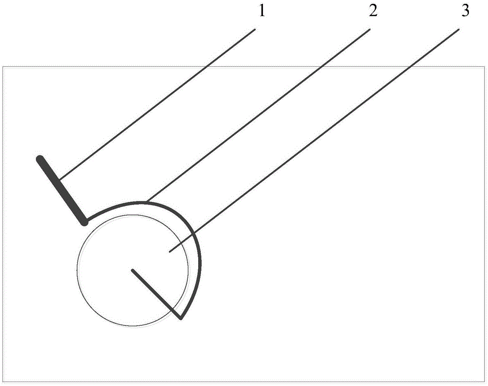
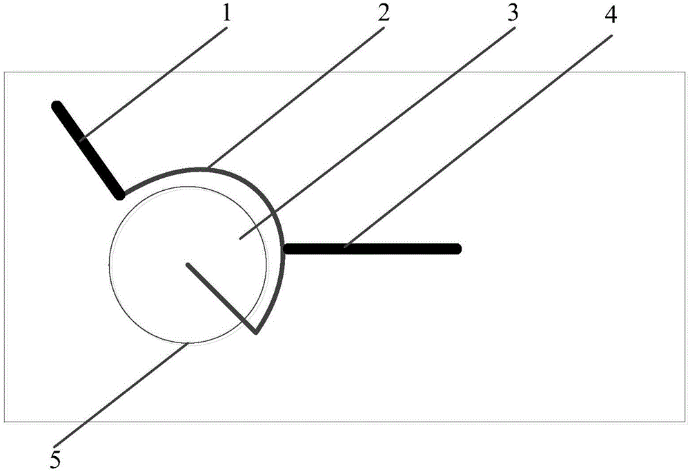
[0027] Such as figure 1 As shown, an embodiment of the present invention provides a PCB, including:

[0028] Wire 1, compensation winding 2 connected to the via hole 2, via hole 3;

[0029] At least one via 3 of the printed circuit board PCB is provided with a compensation winding 2 surrounding the via 3;

[0030] The compensation winding 2 h...


PUM


Abstract

The invention provides a PCB and a circuit board. The PCB comprises a via hole, and a compensation winding wire and a routing wire which are connected with the via hole, wherein the at least one via hole of the PCB is provided with the compensation winding wire surrounding the via hole; the compensation winding wire has no adjacent reference layer; and one end of the routing wire is connected to any position on the compensation winding wire. Through the technical scheme of the PCB and the circuit board, the impedance mismatching problem of the via hole of the PCB can be solved, and thus the signal quality is improved.

Description

Technical field [0001] The invention relates to the technical field of circuit design, in particular to a PCB (Printed Circuit Board, printed circuit board) and a circuit board. Background technique [0002] At present, Server products mostly adopt high-speed multi-board cascade design. Therefore, one or more Connectors will appear on the high-speed wiring path for the interconnection of each board or board and Cable. The pins of the Connector and the corresponding vias on each board The connection is so that the signal is transmitted between the boards. Among them, the connection mode of the high-speed wiring and the via in each board is that the high-speed wiring is directly led out from the via. [0003] However, when the high-speed wiring passes through the Connector, the characteristic impedance value here is too low due to the large capacitance value at the via hole corresponding to the Connector pin, which may cause the characteristic impedance value to exceed the impedance...

Claims


Application Information

Patent Timeline
IPC IPC(8): H05K1/02
CPCH05K1/0251
Inventor 武宁李永翠
Owner LANGCHAO ELECTRONIC INFORMATION IND CO LTD
Learn More