90-degree plate rotating machine
A trigger and plate turning technology, applied in the field of 90-degree plate turning machines, can solve the problems such as inability to apply large-size plate rotation and transportation, complex structure, etc., and achieve the effects of simple structure, reduced labor intensity, and improved work efficiency.
- Summary
- Abstract
- Description
- Claims
- Application Information
AI Technical Summary
Problems solved by technology
Method used
Image

Examples
Embodiment 1
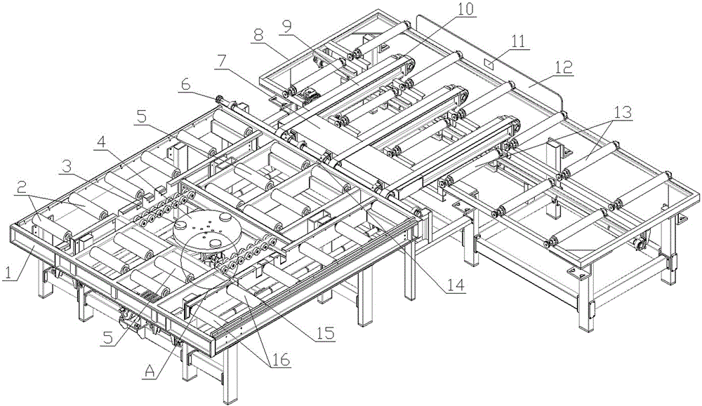
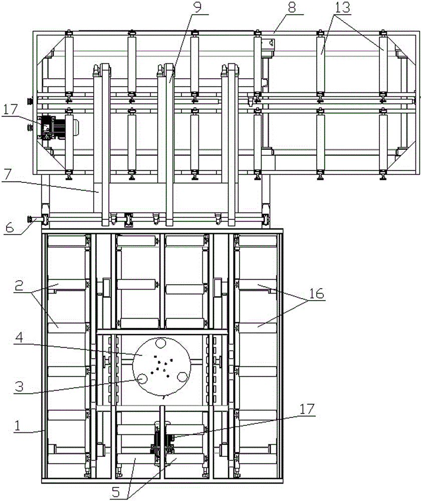
[0039] The 90-degree turntable machine in this embodiment includes a turntable frame and a conveying frame, and the first rubber-coated roller that drives the plate to move along the turntable frame is arranged on the turntable frame. The turntable machine The frame is also provided with a turntable disk for driving the plate to rotate; the conveying frame is provided with a second rubber-covered roller that drives the plate to move along the conveying frame, and the gap between the rotating plate frame and the conveying frame There is a transition conveying device for conveying the plates on the turntable frame to the conveying frame.
Embodiment 2
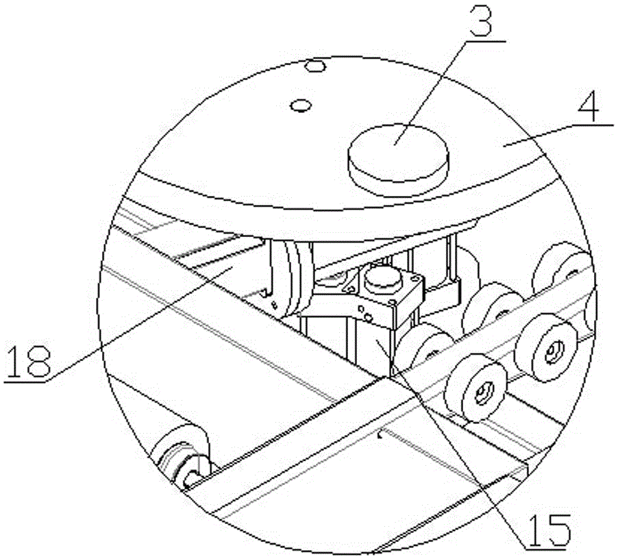
[0041] The 90-degree turntable machine in this embodiment includes a turntable frame and a conveying frame, and the first rubber-coated roller that drives the plate to move along the turntable frame is arranged on the turntable frame. The turntable machine The frame is also provided with a turntable disk for driving the plate to rotate; the conveying frame is provided with a second rubber-covered roller that drives the plate to move along the conveying frame, and the gap between the rotating plate frame and the conveying frame There is a transition conveying device for conveying the plates on the rotating plate frame to the conveying frame; the transition conveying device includes a transmission shaft arranged on the rotating plate frame, and at least two can be hinged on the transmission shaft The lifting arm that rotates along the transmission shaft, the other end of the lifting arm is connected with a pulley, the lower end of the lifting arm at the end of the pulley is equip...
Embodiment 3
[0043] The 90-degree turntable machine in this embodiment includes a turntable frame and a conveying frame, and the first rubber-coated roller that drives the plate to move along the turntable frame is arranged on the turntable frame. The turntable machine The frame is also provided with a turntable disk for driving the plate to rotate; the conveying frame is provided with a second rubber-covered roller that drives the plate to move along the conveying frame, and the gap between the rotating plate frame and the conveying frame There is a transition conveying device for conveying the plates on the rotating plate frame to the conveying frame; the transition conveying device includes a transmission shaft arranged on the rotating plate frame, and at least two can be hinged on the transmission shaft The lifting arm that rotates along the transmission shaft, the other end of the lifting arm is connected with a pulley, the lower end of the lifting arm at the end of the pulley is equip...
PUM
 Abstract
Description
Claims
Application Information
 - R&D
- Intellectual Property
- Life Sciences
- Materials
- Tech Scout
- Unparalleled Data Quality
- Higher Quality Content
- 60% Fewer Hallucinations
Browse by: Latest US Patents, China's latest patents, Technical Efficacy Thesaurus, Application Domain, Technology Topic, Popular Technical Reports.
© 2025 PatSnap. All rights reserved.Legal|Privacy policy|Modern Slavery Act Transparency Statement|Sitemap|About US| Contact US: help@patsnap.com