Sludge heating and drying device

A technology of heating drying and smelting device, applied in the direction of sludge treatment by temperature control, dewatering/drying/concentrating sludge treatment, etc., can solve problems such as deficiencies, and achieve the effects of reducing waste, easy boiling, and increasing specific surface area

Active Publication Date: 2015-11-04
ZHEJIANG SANLIAN ENVIRONMENT MACHINERY EQUIP
View PDF6 Cites 2 Cited by
  • Summary
  • Abstract
  • Description
  • Claims
  • Application Information

AI Technical Summary

Problems solved by technology

Although the current sludge drying treatment methods can achieve a certain degree of dehydration and drying, there are still many deficiencies in terms of drying efficiency, drying degree, and drying uniformity.

Method used


Image

  • Sludge heating and drying device
  • Sludge heating and drying device
  • Sludge heating and drying device

Examples


Embodiment 1

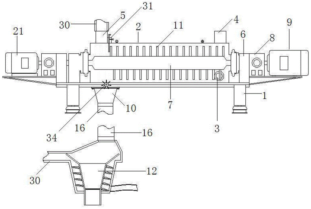
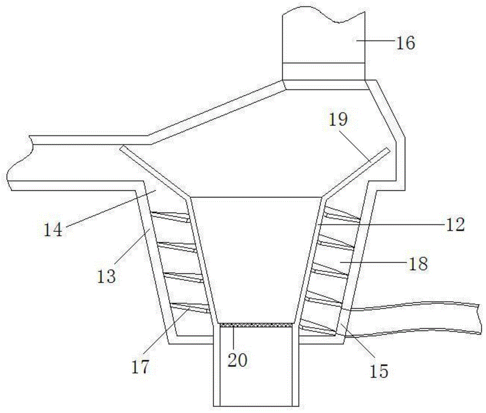
[0023] Embodiment 1: asfigure 1 , figure 2 , Figure 4 , Figure 5 In the shown embodiment, a sludge heating and drying device includes a frame 1, a horizontal drying main cylinder 2, and a dry sludge receiving part. The drying main cylinder is fixed to the frame, and the drying main cylinder There is a sludge feed port 3 on the barrel, and the top of the drying main barrel is provided with a hot flue gas inlet 4 and a wet flue gas outlet 5, and the hot flue gas inlet and the wet flue gas outlet are respectively located near the drying main barrel At the top of both ends, the frame is provided with a bearing seat 6, and the bearing seat is provided with a rotor main shaft 7 matching the bearing seat, and the rotor main shaft is located in the drying main cylinder. The frame is provided with a main shaft drive motor 9 connected to the rotor main shaft through a reducer 8, and a sludge discharge port 10 is provided at the lower part of the drying main cylinder away from the s...

Embodiment 2

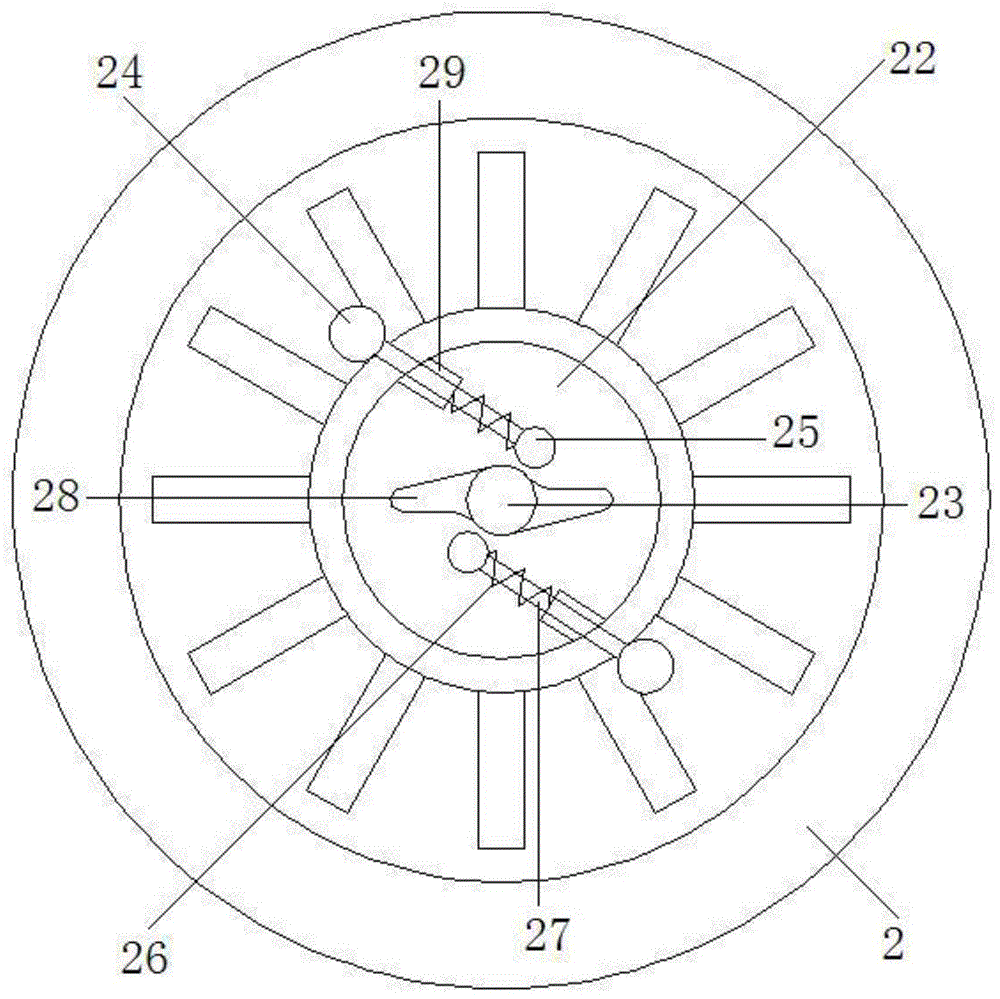
[0025] Embodiment 2: the basic structure and implementation mode of this embodiment are the same as embodiment 1, and its difference is, as image 3 As shown, the frame is provided with a mud-beating motor 21, and the mud-beating motor is located at the end of the rotor main shaft away from the main shaft drive motor, and the described rotor main shaft is provided with a main shaft inner chamber 22, one of which is connected to the rotor. The coaxial transmission inner shaft 23 of the main shaft extends into the inner cavity of the main shaft. One end of the transmission inner shaft is connected with the output shaft of the mud-beating motor, and the other end is connected with the inner shaft bearing. The rotor main shaft is provided with a plurality of The mud beating device, the mud beating device includes a mud ball 24, a stopper 25, a ball receiving spring 26, a slide bar 27, and a slide hole arranged on the main shaft wall, and the slide bar is slidably matched with the s...


PUM


Abstract

The invention discloses a sludge heating and drying device, and aims to the sludge heating and drying device which is capable of carrying out drying treatment on sludge with high moisture content, continuous and stable in drying process, high in drying efficiency, high in integral drying uniformity, and good in drying effect. The sludge heating and drying device comprises a rack, a transverse drying main barrel and a dried sludge receiving part, wherein a a sludge feeding hole, a hot flue gas inlet and a wet flue gas inlet are formed in the drying main barrel; a bearing base is arranged on the rack; a matched rotor main shaft is arranged on the bearing base; a main shaft drive motor which is connected with the rotor main shaft by a speed reducer is arranged on a base frame; a sludge discharge hole is formed in the lower part, far from one end of the sludge feeding hole, of the drying main barrel; and a plurality of stirring and pushing rods are arranged on the rotor main shaft. The sludge heating and drying device has the beneficial effects that: energy resources are reasonably utilized; the drying process is uniform, continuous and efficient; the drying effect is obvious as a secondary drying device is provided; and the working effect in the future can be guaranteed and the service life can be prolonged as a clearing structure is provided.

Description

technical field [0001] The invention belongs to the technical field of sludge treatment, in particular to a sludge heating and drying device. Background technique [0002] A large amount of sludge will be produced in the process of sewage treatment, and the treatment method of these sludges is usually incinerated in a furnace, and the hot flue gas discharged after incineration is about 300 to 400 degrees. Before sludge incineration, the sludge needs to be dried. The initial water content of the sludge is about 75% to 85%. After the treatment, the water content is greatly reduced, and then the incineration operation can be carried out. Although the current sludge drying treatment methods can achieve a certain degree of dehydration and drying, there are still many deficiencies in terms of drying efficiency, drying degree, and drying uniformity. Contents of the invention [0003] In order to overcome the deficiencies in the prior art, the present invention provides a method ...

Claims


Application Information

Patent Timeline
Patent Type & Authority Applications(China)
IPC IPC(8): C02F11/12C02F11/18
Inventor 纪伟勇
Owner ZHEJIANG SANLIAN ENVIRONMENT MACHINERY EQUIP
Why Eureka
Try Eureka