Eureka AIR delivers breakthrough ideas for toughest innovation challenges, trusted by R&D personnel around the world.

Double-station press with upper dies and lower dies for producing glass products

一种双工位、模具的技术,应用在玻璃生产、玻璃的压制、玻璃制造设备等方向,能够解决压床操作工多、限制产量、产品表面异物、灰点多等问题,达到解决操作空间有限、减少碎渣的产生、避免外观损伤的效果

Inactive Publication Date: 2015-11-04
朱保生
View PDF3 Cites 2 Cited by
  • Summary
  • Abstract
  • Description
  • Claims
  • Application Information

AI Technical Summary

Problems solved by technology

[0004] The above-mentioned presses have the following disadvantages: (1) At least 4 molds are required at the same time, generally 5, and a spare
Time-consuming and labor-intensive, and the temperature of the mold cannot be accurately grasped
When the temperature is too low, it is easy to cause the product to burst; on the contrary, when the temperature is too high, the surface of the mold is easily oxidized, and the surface of the product is foggy
(3) Due to the one-way operation of the cutter and the structure of the press bed itself, the width of the blade is relatively large, and the overall stability is poor. Therefore, when cutting the glass rod, a lot of dust and debris are generated. There are more foreign matter and gray spots on the surface of the product
(4) When the product is pressed, the opening of the female mold is upward, and foreign matter such as dust is easy to accumulate
(5) There are many press operators and the operation is cumbersome
(6) There is no function to adjust the product holding time, and the product holding time is not enough, resulting in product shrinkage and deformation, which has a great impact on optical light distribution and poor consistency
(7) Although there are 4 molds installed on the turntable of the 4-station press, there is only one indenter, which limits the output to a certain extent

Method used


Image

  • Double-station press with upper dies and lower dies for producing glass products

Examples


Embodiment Construction

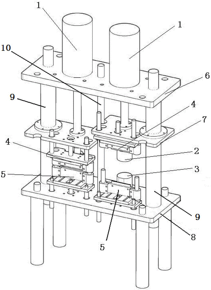
[0024] See figure 1 , the double-station press machine for glass product production provided in this embodiment includes: an upper table 6 and a lower table 8 fixedly arranged up and down, and a pair of hydraulic cylinders 1 (or air cylinders) are arranged on the upper table 6, and the pair of hydraulic cylinders 1 The lower ends of the piston rods of the piston rods are respectively connected with a movable table 7, the bottom surface of each movable table 7 is provided with an upper mold 2, and the lower table 8 is provided with a lower mold 3 coaxial with each upper mold 2 and relatively arranged up and down, each movable table 7 One side of each upper knife rest 4 is provided with an upper knife rest 4, and each upper knife rest 4 is provided with a lower knife rest 5, and upper and lower knife rests are respectively provided with cutting knives suitable for cooperating up and down.

[0025] The upper end of each movable table 7 is provided with an upper cylinder for contr...


PUM


Abstract

The invention relates to a double-station press machine which comprises an upper table top and a lower table top that are fixedly arranged vertically, wherein a pair of hydraulic cylinders is arranged on the upper table top; lower ends of piston rods of the hydraulic cylinders are connected with moving table tops respectively; an upper mould is arranged on the bottom surface of each of the moving table tops; a lower mould which is coaxial with and opposite to each of the upper moulds is arranged on the lower table top; an upper cutter saddle is arranged on one side of each of the moving table tops; a lower cutter saddle is arranged under each of the upper cutter saddles; and cutters suitable for matching vertically are arranged on the upper and lower cutter saddles. The double-station press machine solves the problems that the product surface has break marks, wrinkles, shrinkage and deformation, the yield is low, and the operation is complicated when glasswork with high requirements, such as an optical glass lens, is produced in the prior art. With the adoption of the double-station press machine, the product qualification rate and the yield are increased and the working load is reduced. The practical data shows that the product qualification rate is increased by about 30% and the yield is increased by about 25%.

Description

technical field [0001] The invention relates to the field of glass machinery manufacturing, and relates to a double-station press for glass product production, which is mainly used for the production of optical glass lenses and glass products for vehicle lamps, street lamps, industrial and mining lamps, solar energy, and household lighting fixtures. Background technique [0002] In the prior art, when producing high-demand glass products such as optical glass lenses, there are problems such as gray spots on the product surface, wrinkles, shrinkage, deformation, low output, and cumbersome operations. [0003] The machine tool of the existing 4-station press in the optical glass lens and glass products industry is composed of hydraulic system, electrical system, rotating device (turntable), pneumatic components and other parts. The working process is to connect the power supply and air source- 4 molds are placed in the electric furnace in turn for heating--Install the molds on...

Claims


Application Information

Patent Timeline
Patent Type & Authority Applications(China)
IPC IPC(8): C03B11/00
CPCY02P40/57
Inventor 不公告发明人
Owner 朱保生
Why Eureka
Eureka Blog
Learn More