Tempering furnace material rack slideway mechanism

A tempering furnace and slideway technology, applied in furnaces, heat treatment furnaces, furnace types, etc., can solve the problems of reduced work efficiency, disorderly arrangement of shaft workpieces, difficult manual operation, etc., and save man-hours and work efficiency of tempering treatment. The effect of improving and reducing production costs

Active Publication Date: 2015-11-04
SHANGHAI JINGZHI IND CO LTD
View PDF4 Cites 2 Cited by
  • Summary
  • Abstract
  • Description
  • Claims
  • Application Information

AI Technical Summary

Problems solved by technology

[0004] Since the models of shaft workpieces are often long and short, such as figure 1 As shown, the feed inlet 1 of the tempering furnace machine tool in the prior art is just a slide plate arranged obliquely, and there is no mechanism for guiding the shaft workpieces, so that the arrangement of the shaft workpieces is very messy when sliding into the conveyor belt of the tempering furnace machine tool, and it must be It is necessary to manually arrange the messy shaft workpieces on the conveyor belt; while the working temperature of the tempering furnace machine tool inlet is generally around 300°C, the high temperature environment makes manual operation very difficult, and the same worker cannot bear the high temperature for a long time operation, which is bound to greatly reduce work efficiency, but also increases the labor intensity of workers and the production cost of shaft workpieces

Method used


Image

  • Tempering furnace material rack slideway mechanism
  • Tempering furnace material rack slideway mechanism
  • Tempering furnace material rack slideway mechanism

Examples


Embodiment Construction

[0037] The implementation of the present invention will be illustrated by specific specific examples below, and those skilled in the art can easily understand other advantages and effects of the present invention from the contents disclosed in this specification.

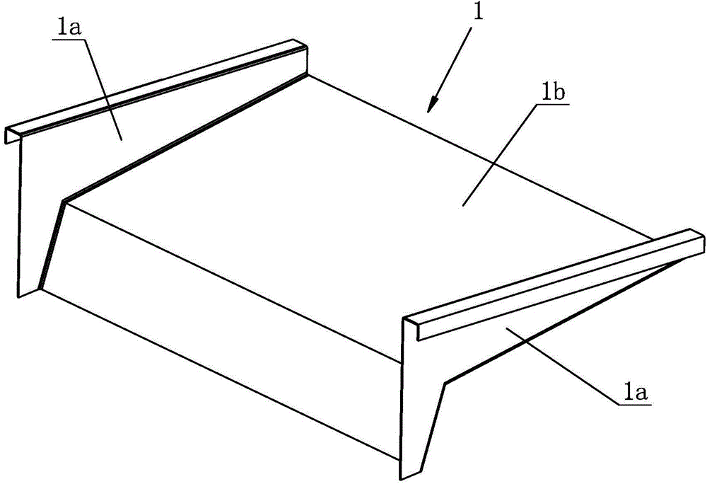
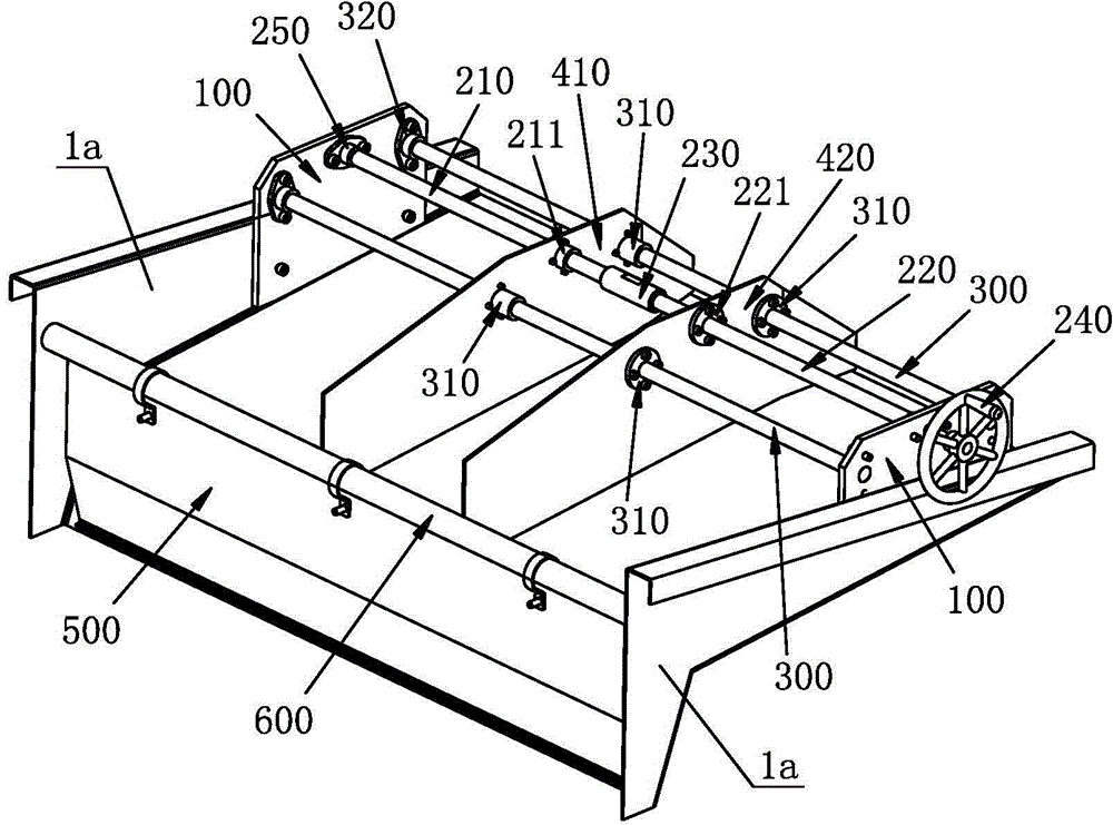
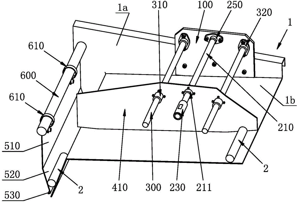
[0038] see Figure 1 to Figure 3 . It should be noted that the structures, proportions, sizes, etc. shown in the drawings attached to this specification are only used to match the content disclosed in the specification, for those who are familiar with this technology to understand and read, and are not used to limit the implementation of the present invention. Limiting conditions, so there is no technical substantive meaning, any modification of structure, change of proportional relationship or adjustment of size, without affecting the effect and purpose of the present invention, should still fall within the scope of the present invention. The disclosed technical content must be within the scope covered. At the sa...


PUM

PropertyMeasurementUnit
diameteraaaaaaaaaa

Abstract

The invention provides a tempering furnace material rack slideway mechanism which comprises a support, a slideway baffle and a discharging baffle, wherein two support plates of the support are respectively and fixedly arranged on two side walls of a feeding hole of a tempering furnace machine tool, a two-way screw rod and at least one guide rod are arranged between the two support plates, and the slideway baffle comprises a first baffle and a second baffle which are parallelly arranged between the two support plates; the slideway for feeding shaft workpieces is formed between the first baffle and the second baffle, the two-way screw rod and the guide rod respectively penetrate through the slideway baffle, and the first baffle and a left screw cap arranged on the two-way screw rod are fixed together; the second baffle and a right screw cap arranged on the two-way screw rod are fixed together, the first baffle and the second baffle are respectively provided with a guide sleeve matched with a guide rod, and the discharging baffle is arranged on the tail of the feeding hole; and the upper end of the discharging baffle is fixed, and a V-shaped charging groove is formed between the lower end of the discharging baffle and the tail end of a bottom plate of the feeding hole. The axial limiting and radial positioning for shaft workpieces with different lengths are realized, the tempering furnace machine tool is high in automation degree and high in working efficiency, and the production cost of shaft workpieces is low.

Description

technical field [0001] The invention relates to a tempering furnace machine tool for heat treatment of shaft workpieces, in particular to a tempering furnace charge rack slideway mechanism. Background technique [0002] Many shaft workpieces need to be tempered after machining. Tempering treatment can improve the structural stability of shaft workpieces, so that the shaft workpieces will no longer undergo organizational transformation during use, so that the geometric dimensions and The performance remains stable; it can also eliminate the internal stress of the shaft workpiece, improve the performance of the shaft workpiece and stabilize the geometric size of the workpiece; in addition, it can also adjust the mechanical properties of the shaft workpiece material to better meet the use requirements. [0003] Because the shaft workpieces are often mass-produced, it is often necessary to configure a special tempering furnace machine tool for the shaft workpieces, so that the s...

Claims


Application Information

Patent Timeline
Patent Type & Authority Applications(China)
IPC IPC(8): C21D9/28
Inventor 邓南建张福田胡建雷金月琴马小伟
Owner SHANGHAI JINGZHI IND CO LTD
Why Eureka
Try Eureka