
Electroplating bath

A technology of electroplating tank and electroplating solution, which is applied in the direction of plating tank, etc., and can solve problems such as disordered force, uneven copper thickness of board parts, and increased electroplating cost

Active Publication Date: 2015-11-04
迈瑞凯电子科技(天津)有限公司
View PDF7 Cites 7 Cited by
  • Summary
  • Abstract
  • Description
  • Claims
  • Application Information

AI Technical Summary

Problems solved by technology

[0003] However, the jet flow and turbulent pulsation generated by the circulation mode of the traditional electroplating tank, the force of the jet flow and turbulent pulsation around the printed circuit board is disordered, which may easily cause uneven copper thickness of the board and increase the cost of electroplating

Method used


Image

  • Electroplating bath
  • Electroplating bath
  • Electroplating bath

Examples


Embodiment Construction

[0022] In order to make the above objects, features and advantages of the present invention more comprehensible, specific implementations of the present invention will be described in detail below in conjunction with the accompanying drawings. In the following description, numerous specific details are set forth in order to provide a thorough understanding of the present invention. However, the present invention can be implemented in many other ways different from those described here, and those skilled in the art can make similar improvements without departing from the connotation of the present invention, so the present invention is not limited by the specific implementations disclosed below.

[0023] It should be noted that when an element is referred to as being “fixed” to another element, it can be directly on the other element or there can also be an intervening element. When an element is referred to as being "connected to" another element, it can be directly connected ...


PUM


Abstract

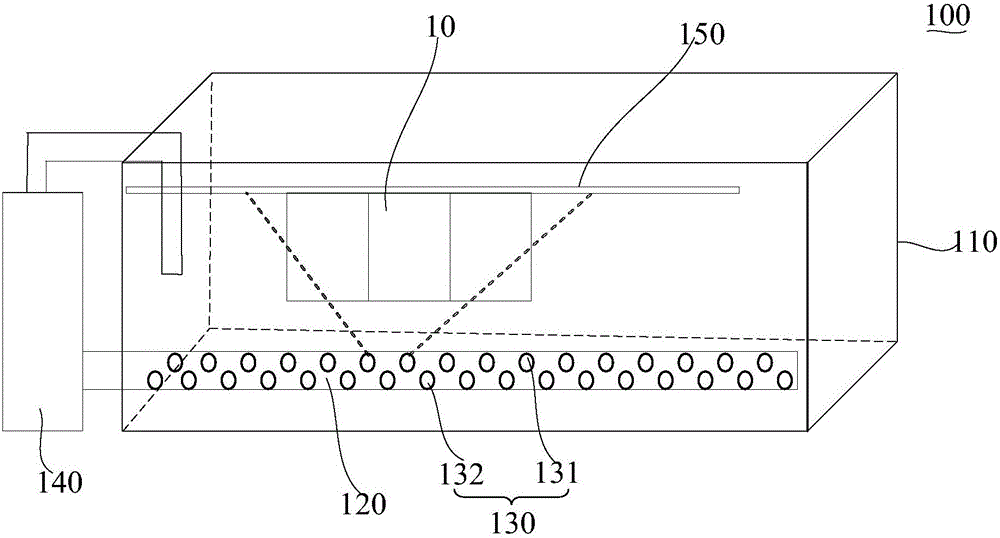
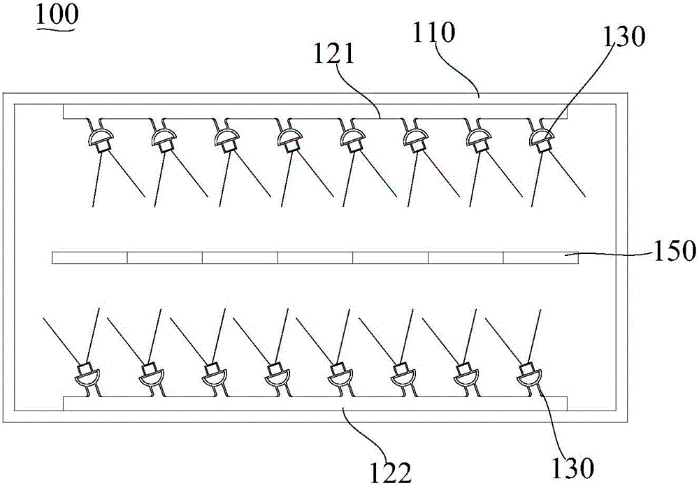
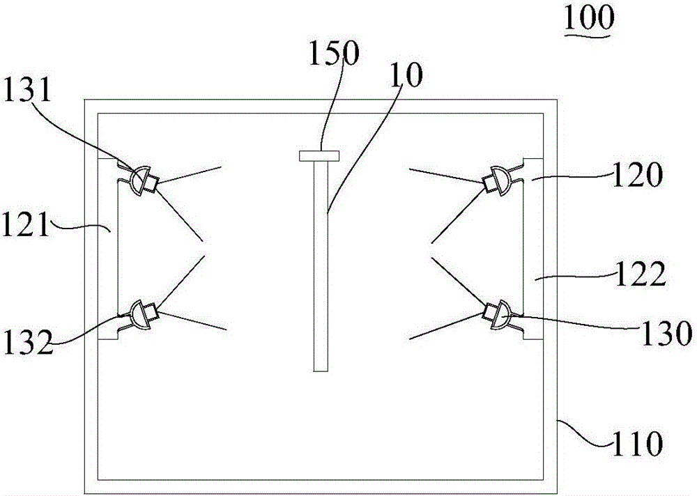
The invention relates to an electroplating bath for electroplating a to-be-plated board. The electroplating bath comprises a bath body for containing electroplating liquid, a plurality of guide tubes and a plurality of nozzles. The to-be-plated board is accommodated by the bath body. The guide tubes are arranged on the two sides of the bath body. The nozzles are arranged on the guide tubes and arranged in rows along the guide tubes. The electroplating liquid flows in the guide tubes and is sprayed out through the nozzles. The outflow direction of each row of nozzles faces the to-be-plated board. The included angle between the outflow direction of the nozzles and the to-be-plated board ranges from 40 degrees to 50 degrees. The electroplating liquid in the electroplating bath is sprayed around the to-be-plated board; the electroplating liquid around the to-be-plated board is evenly and quickly supplemented; the temperature, concentration, pH value and the like of the electroplating liquid around the to-be-plated board are kept consistent; other chemical compositions are evenly scattered, so that the thickness of an electroplating layer deposited on the board face of the to-be-plated board is kept consistent; and the purpose of reducing the production cost is achieved.

Description

technical field [0001] The invention relates to an electroplating device, in particular to an electroplating tank. Background technique [0002] At present, the electroplating tank for printing the plate to be plated often uses an air compressor to directly spray impurity-free air compressed by high pressure into the bath liquid through the air jet tube group connected to the bottom of the tank, so that the bubbles pass through the liquid layer in strings, and the jet flow The entrainment and turbulent pulsation of the liquid make the temperature and concentration of the bath liquid quickly and uniformly. [0003] However, the jet flow and turbulent flow pulsation generated by the circulation mode of the traditional electroplating tank, the force of the jet flow and turbulent flow pulsation around the printed circuit board is disordered, which may easily cause uneven copper thickness of the board and increase the cost of electroplating. Contents of the invention [0004] ...

Claims


Application Information

Patent Timeline
IPC IPC(8): C25D17/02C25D5/08
Inventor 雷岩
Owner 迈瑞凯电子科技(天津)有限公司
Learn More