
Pressure Stabilization Technology for Improving the Cementing Quality of High Temperature and High Pressure Wells

A high temperature and high pressure, well cementing technology, applied in wellbore/well components, sealing/isolation, earth-moving drilling, etc. Achieve the effect of reducing the risk of a large amount of fluid intrusion and shortening the waiting time

Active Publication Date: 2017-07-28
CHINA NAT OFFSHORE OIL CORP +1
View PDF7 Cites 0 Cited by
  • Summary
  • Abstract
  • Description
  • Claims
  • Application Information

AI Technical Summary

Problems solved by technology

[0002] In the cementing operation of high-temperature and high-pressure wells in oil exploration and development, when cementing operations in high-temperature and high-pressure well sections, especially in high-pressure and low-permeability formations, because the predicted formation pressure is lower than the actual one, the fluid will The column cannot stabilize the formation and the formation fluid invades the cement slurry, resulting in tiny gaps between the cement and the formation, cement and casing, and the cementing quality is unqualified. In severe cases, the high-pressure section cannot be effectively sealed, and oil exploration cannot be achieved. The purpose of development, resulting in waste of manpower, property and equipment resources

Method used


Image

  • Pressure Stabilization Technology for Improving the Cementing Quality of High Temperature and High Pressure Wells

Examples


Embodiment 1

[0013] Embodiment 1 is realized according to the following steps:

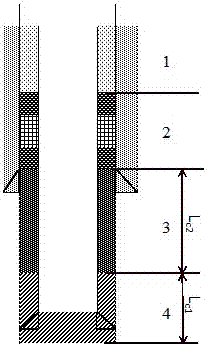
[0014] 1. According to the specific gravity of the actual drilling mud and the measured or predicted formation pressure coefficient and formation fracture pressure coefficient, comprehensively consider the weightlessness pressure at the critical point of the cement slurry to ensure that the pressure stability coefficient is not less than 1.0 while not leaking.

[0015] Set formation pressure coefficient as ρ f , the burst pressure coefficient is ρ p , then the formation pressure P f =ρ f gH, Pp=ρ p gH, then, the voltage stability coefficient p is calculated according to the following formula:

[0016]

[0017] Among them, P cmk is the slurry column pressure of the cement slurry in the static glue of 150Pa, MPa; P f is formation pressure, MPa; P cm is the initial annular liquid column pressure, MPa, P cm flw is the weight loss pressure at the critical point of cement slurry, MPa.

[0018] 2. In term...

Embodiment 2

[0020] Example 2 Application of actual drilling operations.

[0021] 1. In a drilling operation, the polymer cement slurry system is used, the predicted formation pressure coefficient is 1.62sg, the formation fracture pressure coefficient is 1.95sg, the cement slurry specific gravity is 2.0sg, the slurry column length is 880m, the annular drilling fluid specific gravity is 1.63sg, and the fluid column The length is 1900m, the specific gravity of the front fluid is 1.0sg, the length of the liquid column is 816m (the flushing fluid is 510m, the spacer fluid is 306m), and the weight loss pressure at the critical point of the cement slurry is 2.95MPa.

[0022] 2. According to the calculation formula of pressure stability coefficient p in embodiment 1:

[0023] , the calculated pressure stability coefficient p=0.92.

[0024] Since the pressure stability coefficient p is less than 1.0, the following measures are used to adjust to ensure that the pressure stability coefficient is ...


PUM


Abstract

The invention discloses a pressure stabilization process for improving the cementing quality of high-temperature and high-pressure wells. The pressure stabilization process mainly includes the following two steps: on the one hand, according to the predicted or actually measured formation pressure, determine a reasonable weighted pre-fluid (flush fluid, spacer fluid) to achieve the purpose of balancing the formation pressure; on the other hand, double-setting or multi-setting cement slurry column structure is adopted, the cement slurry is continuously sealed, and different initial setting times are designed for the head and tail slurry to determine a reasonable cement slurry column structure . The invention can reduce the risk of formation fluid invasion and improve the cementing quality, and the pressure stabilization process can be widely used in various petroleum exploration and development fields.

Description

technical field [0001] The invention belongs to drilling technology in petroleum exploration and development, and relates to a cementing process for high-temperature and high-pressure wells, in particular to a pressure stabilization process for improving the cementing quality of high-temperature and high-pressure wells. Background technique [0002] In the cementing operation of high-temperature and high-pressure wells in oil exploration and development, when cementing operations in high-temperature and high-pressure well sections, especially in high-pressure and low-permeability formations, because the predicted formation pressure is lower than the actual one, the fluid will The column cannot stabilize the formation and the formation fluid invades the cement slurry, resulting in tiny gaps between the cement and the formation, cement and casing, and the cementing quality is unqualified. In severe cases, the high-pressure section cannot be effectively sealed, and oil explorati...

Claims


Application Information

Patent Timeline
Patent Type & Authority Patents(China)
IPC IPC(8): E21B33/13
Inventor 李中李炎军李云龙邵诗军张万栋罗东辉肖伟陈浩东王巍朱新华谢露
Owner CHINA NAT OFFSHORE OIL CORP
Learn More