
A network physical isolation device

A physical isolation and network technology, applied in the protection of internal/peripheral computer components, etc., can solve problems such as difficulty in closing or opening, computer intrusion risk, etc., and achieve the effect of reducing risks

Active Publication Date: 2017-01-11
TONGFANG COMP
View PDF6 Cites 0 Cited by
  • Summary
  • Abstract
  • Description
  • Claims
  • Application Information

AI Technical Summary

Problems solved by technology

These controllers are located independently of each other on the motherboard of the personal computer and are usually difficult to turn off or turn on together
Failure to turn off all wireless connections at the same time presents a risk of computer intrusion

Method used


Image

  • A network physical isolation device
  • A network physical isolation device

Examples


Embodiment 1

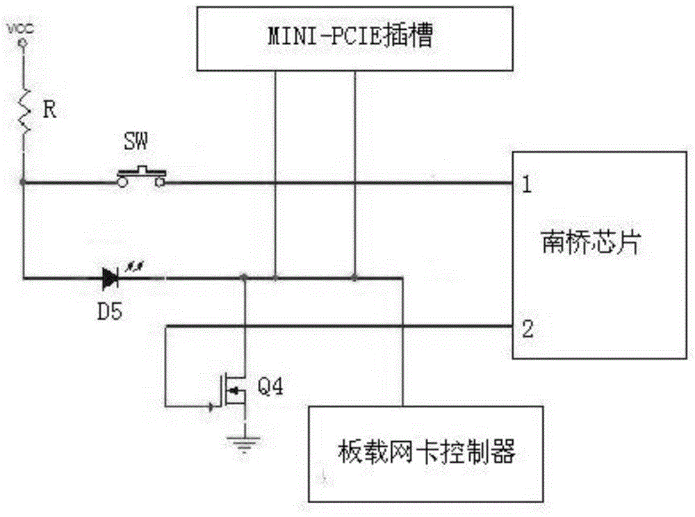
[0012] Embodiment 1: The south bridge chip of the computer motherboard has multiple GPIO ports, which can be used as input or output high and low levels. The onboard network card controller on the motherboard can receive external signals to close or start the Bluetooth connection, and the 51st pin of the MINI-PCIE slot on the motherboard also has the ability to receive external signals to close the wireless WIFI network card in the slot and the function of the bluetooth network card. The source of the NMOS transistor Q4 is grounded, its gate is connected to the second GPIO port 2 of the south bridge chip PCH, and its drain is connected to the 51st pin of the MINI-PCIE slot and the 20th pin of the onboard network card controller. The six pins and the cathode of LED D5 are connected together. The first GPIO port 1 of the south bridge chip is connected to one end of the switch SW. The other end of the switch SW is connected to the anode of the light emitting diode D5 and one en...

Embodiment 2

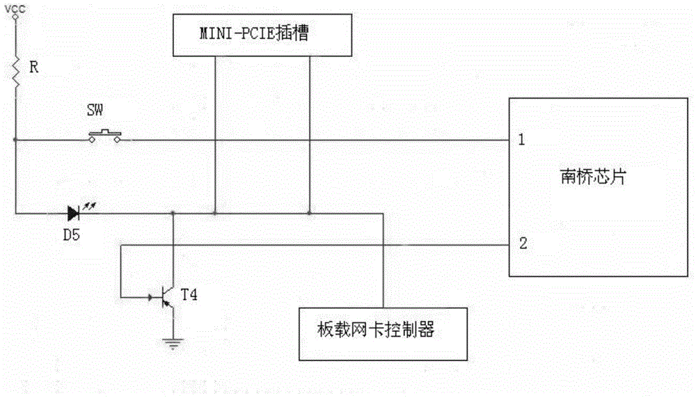
[0015] Example 2: The emitter of the NPN transistor T4 is grounded, its collector is connected to the second GPIO port 2 of the south bridge chip PCH, and its base is connected to the 51st pin of the MINI-PCIE slot, the on-board network card The twenty-sixth pin of the controller and the negative electrode of the light-emitting diode D5 are connected together. The first GPIO port 1 of the south bridge chip is connected to one end of the switch SW. The other end of the switch SW is connected to the anode of the light emitting diode D5 and one end of the bias resistor. The other end of the bias resistor R is connected to the power supply VCC.

[0016] The switch SW is in a normally open state. When the user presses the switch SW to close it, the first GPIO port 1 is pulled up to a high level through the bias resistor R, and the south bridge chip simultaneously changes the voltage of the second GPIO port 2 to a high level. Therefore, the transistor T4 is turned on, and the fif...


PUM


Abstract

The invention discloses a network physical isolation device. The network physical isolation device comprises a south-bridge chip, a first GPIO (general purpose input / output) port of the south-bridge chip is connected with one end of a switch, a second GPIO port of the south-bridge chip is connected with a control electrode of a switch tube, a first connecting electrode of the switch tube is grounded, a second connecting electrode of the switch tube is connected with a negative electrode of a light emitting diode, a positive electrode of the light emitting diode and the other end of the switch are jointly connected with one end of a bias resistor, the other end of the bias resistor is connected with a power source, and the output end of the integral isolation device is arranged at the negative electrode of the light emitting diode. A wireless local area network card in a MINI PCIE (peripheral component interface express) slot and a Bluetooth controller can be turned off at the same time by matching of the GPIO port of the south-bridge chip and the external switch, the switch tube and the light emitting diode, and risk of network invasion of computers is reduced.

Description

technical field [0001] The invention relates to a network physical isolation device, belonging to the field of personal computers. Background technique [0002] With the continuous development and progress of science and technology, more and more secret-related departments have established internal computer networks. Because these internal networks involve a lot of secret information, security and confidentiality are an important part in the construction of the internal network. Secret-related departments at all levels have also formulated and adopted corresponding systems and measures for this purpose. Among them, it is an important measure to stipulate that the intranet must be physically separated from the public network. [0003] A PC's wired network connection is easier to physically isolate. However, there are many types of wireless network connections, such as WIFI, Bluetooth and so on. Each wireless communication protocol has its own transceiver controller. These...

Claims


Application Information

Patent Timeline
Patent Type & Authority Patents(China)
IPC IPC(8): G06F21/70
CPCG06F21/72
Inventor 辛尧辰杨蔚才万贵平
Owner TONGFANG COMP
Learn More