Efficient heat regenerative system and method

A heat recovery system and high-efficiency technology, applied in the power field, can solve problems such as boiling, low exhaust back pressure, and cavitation of feed water pumps

Active Publication Date: 2015-11-04
CHINA ENERGY ENG GRP GUANGDONG ELECTRIC POWER DESIGN INST CO LTD
View PDF7 Cites 4 Cited by
  • Summary
  • Abstract
  • Description
  • Claims
  • Application Information

AI Technical Summary

Problems solved by technology

[0002] In order to improve the thermal cycle efficiency of thermal power generation units, steam turbines generally adopt heat recovery technology, that is, a part of the steam that has done a certain amount of work is extracted from the intermediate stage of the main steam turbine, and supplied to the recovery equipment to heat boiler feed water. Traditional large-capacity thermal power generation units The water pump is usually a pure condensing feed water pump turbine. The pure condensing feed water pump turbine itself does not have steam extraction, the exhaust steam back pressure is low, the humidity is high, and the efficiency of the last few stages of blades is low. Therefore, the efficiency of the pure condensing feed water pump turbine itself and The overall efficiency of unit heat recovery is often not high
A new solution is to use an extraction backpressure feedwater pump turbine, but the exhaust pressure of the backpressure feedwater pump turbine will affect the exhaust steam humidity of the feedwater pump turbine, thereby affecting its operating efficiency. In order to stabilize the feedwater pump For the exhaust steam pressure of the steam turbine, there is a way to install a steam flow balance pipe connecting the exhaust pipe of the intermediate pressure cylinder of the main steam turbine and the exhaust pipe of the steam turbine of the feed water pump in the system. Exhaust pipe for steam replenishment;

Method used


Image

  • Efficient heat regenerative system and method

Examples


Embodiment Construction

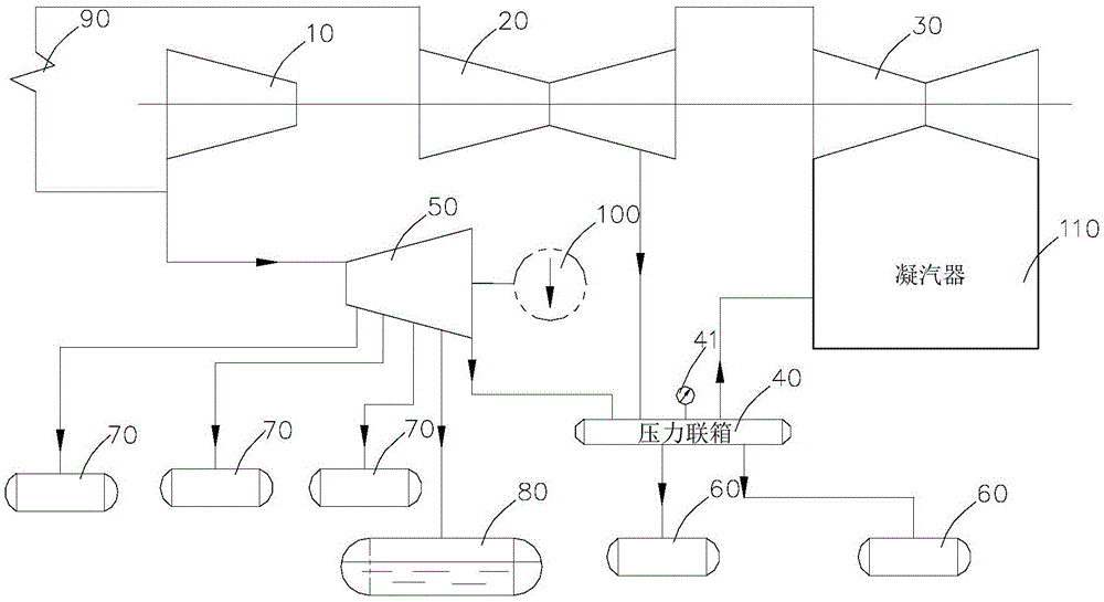
[0026] Such as figure 1 As shown, a high-efficiency heat recovery system includes a high-pressure cylinder 10, a medium-pressure cylinder 20, and a low-pressure cylinder 30 connected in sequence, and it also includes a pressure header 40 and an extraction backpressure type feedwater pump turbine 50. The medium-pressure The cylinder 20 is provided with at least one steam extraction port, the pressure header 40 is provided with at least two steam inlets, and one of the steam extraction ports of the medium pressure cylinder 20 communicates with one of the steam inlets of the pressure header 40, The exhaust port of the feedwater pump turbine 50 communicates with the other steam inlet port of the pressure header 40, and the steam exhaust port of the pressure header 40 communicates with the steam inlet port of the heat recovery equipment such as the low-pressure heater 60 or the deaerator 80. The steam inlet of the feedwater pump turbine 50 is connected with the exhaust outlet of th...


PUM


Abstract

The invention relates to an efficient heat regenerative system and method. The efficient heat regenerative system comprises a high pressure cylinder, an intermediate pressure cylinder and a low pressure cylinder which are communicated in sequence. The efficient heat regenerative system further comprises a pressure header and an extraction back-pressure type feed pump turbine. The pressure header is provided with at least two steam inlets. One steam extraction opening of the intermediate pressure cylinder is communicated with one steam inlet of the pressure header. A steam exhaust outlet of the feed pump turbine is communicated with the other steam inlet of the pressure header. A steam exhaust outlet of the pressure header is communicated with a steam inlet of each heat regenerative device. A steam inlet of the feed pump turbine is communicated with a steam exhaust outlet or a steam extraction opening of the high pressure cylinder or the other steam extraction opening of the intermediate pressure cylinder. The steam exhaust pressure of the feed pump turbine is controlled by normal steam exhaust of the feed pump turbine, steam extraction and supplementation of the intermediate pressure cylinder and an overflow system, and exhaust back pressure can be effectively controlled within a reasonable value under the condition that the pressure of the pressure header is fixed and a unit has different loads. The steam exhaust humidity can be guaranteed, efficient operation of the feed pump turbine is ensured, and the problems of overpressure of a deaerator and cavitation of a feed pump are avoided.

Description

technical field [0001] The invention relates to electric power technology, in particular to a high-efficiency heat recovery system and method. Background technique [0002] In order to improve the thermal cycle efficiency of thermal power generation units, steam turbines generally adopt heat recovery technology, that is, a part of the steam that has done a certain amount of work is extracted from the intermediate stage of the main steam turbine, and supplied to the recovery equipment to heat boiler feed water. Traditional large-capacity thermal power generation units The water pump is usually a pure condensing feed water pump turbine. The pure condensing feed water pump turbine itself does not have steam extraction, the exhaust steam back pressure is low, the humidity is high, and the efficiency of the last few stages of blades is low. Therefore, the efficiency of the pure condensing feed water pump turbine itself and The overall efficiency of unit heat recovery is often not...

Claims


Application Information

Patent Timeline
IPC IPC(8): F01K17/02
CPCY02E20/14
Inventor 张鹏张玲葛蕾李伟科范永春乐自知邓广义
Owner CHINA ENERGY ENG GRP GUANGDONG ELECTRIC POWER DESIGN INST CO LTD
Why Eureka
Try Eureka