
Air intake muffler for turbocharged engine

A technology of intake muffler and turbocharging, applied in the direction of intake muffler, etc., can solve the problems of limited engine room space, limited noise reduction frequency band, high cost, etc., to avoid vibration and radiation noise, wide noise reduction frequency band, compact effect

Active Publication Date: 2017-11-28
CHONGQING CHANGAN AUTOMOBILE CO LTD
View PDF6 Cites 0 Cited by
  • Summary
  • Abstract
  • Description
  • Claims
  • Application Information

AI Technical Summary

Problems solved by technology

However, the methods of reducing engine intake noise are limited to increasing the volume of the air filter housing, lengthening the intake pipe, increasing the Holm Hertz resonance cavity, etc.
Although these methods can effectively reduce intake noise, they will take up a lot of space in the engine compartment
However, the space in the engine compartment is often very limited, and it is difficult to arrange various large-capacity noise reduction components in an extremely limited space.
The use of braided tubes can reduce noise without increasing the occupied space, but because of the high cost of braided tubes, many car manufacturers are discouraged from using braided tubes
Therefore, the current methods for reducing the intake noise of the engine all have the problems that the noise reduction and the cabin space cannot be balanced and the cost is high
At the same time, except for the braided tube, the current noise reduction technology has a very limited noise reduction frequency band, especially for some medium and high frequency noise, which can be said to be completely powerless

Method used


Image

  • Air intake muffler for turbocharged engine
  • Air intake muffler for turbocharged engine

Examples


Embodiment Construction

[0019] The present invention will be further described below in conjunction with accompanying drawing.

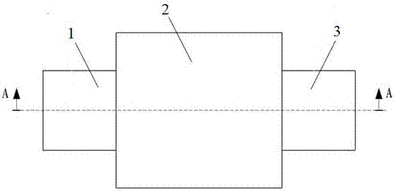
[0020] Such as figure 1 The shown air intake muffler for a turbocharged engine includes an intake pipe 1, an air outlet pipe 3 and a housing 2. The housing 2 has an input wall and an output wall, and the air outlet pipe 3 communicates with the intake system of the engine.

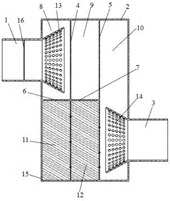
[0021] Such as figure 2 As shown, the shell 2 is provided with a first partition 4, a second partition 5, a third partition 6 and a fourth partition 7, and the second through holes are evenly distributed on these partitions. The third partition 6 and the fourth partition 7 are in the same plane. The first partition 4 and the input wall define the left chamber, the second partition 5 and the output wall define the right chamber 10, the first partition 4 and the second partition 5 define the middle chamber, and the third partition 6 divides the left chamber into a first chamber 8 and a third chamber 11...


PUM


Abstract

The invention relates to an intake muffler for a turbocharged engine, which includes an air intake pipe, an air outlet pipe and a casing, the casing has an input wall and an output wall, and the casing is provided with a first partition, a second partition, a third partition, The right chamber, the first chamber, the second chamber, the third chamber and the fourth chamber defined by the fourth partition, the input wall and the output wall; the output end of the air inlet pipe is located in the first chamber, and the air outlet pipe The input end of the input is located in the right chamber; the third chamber is located below the first chamber, the fourth chamber is located below the second chamber, the third chamber and the fourth chamber are filled with sound-absorbing materials, and the third chamber is located below the second chamber. The bottom of the chamber is provided with drainage holes communicating with the outside of the casing; second through holes are evenly distributed on the first partition, the second partition, the third partition and the fourth partition. The invention has the advantages of compact structure, small volume, low cost and wide noise reduction frequency band; at the same time, it effectively avoids the vibration and radiation noise caused by gas impacting the casing.

Description

technical field [0001] The invention relates to a muffler, in particular to an intake muffler for a turbocharged engine. Background technique [0002] With the development of the automobile industry, people have higher and higher requirements on the power, economy and comfort of automobiles. In order to improve the performance of the engine and reduce the noise of the intake system, not only the inherent parameters of the intake muffler itself must be considered in the design process of the vehicle intake muffler, but also the layout position and structure of the intake muffler must be rationally optimized. [0003] In addition to filtering the air, the air filter is also a kind of intake muffler. At present, the air filters used in cars all adopt the design method of three-stage connection. However, the methods for reducing engine intake noise are limited to increasing the volume of the air filter housing, lengthening the intake pipe, and increasing the Holm Hertz resonan...

Claims


Application Information

Patent Timeline
Patent Type & Authority Patents(China)
IPC IPC(8): F02M35/12
Inventor 吴明江王奋吴斌程齐麟
Owner CHONGQING CHANGAN AUTOMOBILE CO LTD
Learn More