Rotary magnetic propeller

A thruster and rotary technology, applied in propulsion systems, electrical components, electromechanical devices, etc., can solve problems such as thrust reduction, and achieve stable and reliable motion, convenient control, and low power consumption

Active Publication Date: 2015-11-04
CHANGZHOU INST OF TECH
View PDF7 Cites 3 Cited by
  • Summary
  • Abstract
  • Description
  • Claims
  • Application Information

AI Technical Summary

Problems solved by technology

In this application, the magnitude of the thrust is inversely proportional to the square of the distance. When the stroke distance is long, the thrust will be significantly reduced, and it can only be applied to occasions where the propulsion distance is relatively short.

Method used


Image

  • Rotary magnetic propeller
  • Rotary magnetic propeller
  • Rotary magnetic propeller

Examples


Embodiment

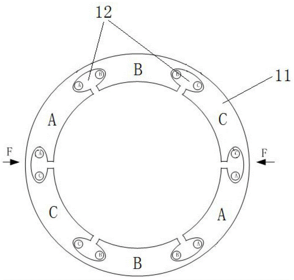
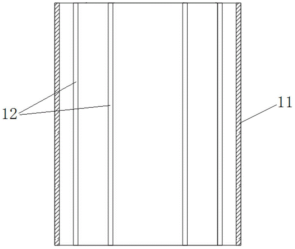
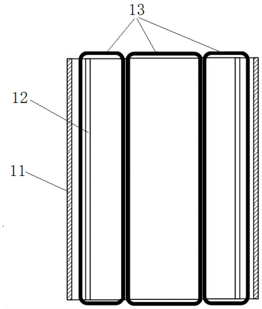
[0038] see Figure 1 to Figure 10 As shown, a rotary magnetic thruster of this embodiment includes a casing, a static magnetic pole 1, a moving magnetic pole 2, a propulsion rod 3 and a drive circuit. The static magnetic pole 1 includes a magnetic circuit ring 11 and a coil 13. On the magnetic circuit ring 11 There are six groups of coil installation grooves 12 evenly distributed along the circumferential direction, the coil installation grooves 12 penetrate the axial direction of the magnetic circuit ring 11, the coil installation grooves 12 are oval, and are provided with an opening to the inside to form a magnetic claw, each A coil installation slot 12 can accommodate two coils, and two adjacent coil installation slots 12 are provided with a group of coils 13 (such as image 3 As shown), each coil 13 is the same, and the same-named ends of the two sets of coils 13 opposite to each other on the magnetic circuit ring 11 are connected, so that after the current is applied, the m...


PUM


Abstract

The invention discloses a rotary magnetic propeller, and belongs to the field of electromagnetic technologies. The rotary magnetic propeller comprises a shell, a static magnetic pole, a dynamic magnetic pole, a propelling lever and driving circuits, and is characterized in that the static magnetic pole comprises a magnetic circuit ring and coils, the magnetic circuit ring is provided with six groups of coil mounting grooves which are uniformly distributed along the circumferential direction, the coil mounting grooves penetrate along the axial direction of the magnetic circuit ring, a group of coils is arranged in two adjacent coil mounting grooves, and corresponding terminals of two groups of coils, which are opposite in position on the magnetic circuit ring, are connected; the dynamic magnetic pole comprises a permanent magnet magnetic ring, and the magnetic flux direction of the permanent magnet magnetic ring is the diameter direction of the permanent magnet magnetic ring; the propelling lever is provided with a spiral orbit which is matched with a ball of a shell seam allowance portion; and each two groups of coils, whose corresponding terminals are connected, are provided with a driving circuit which independently controlling the current direction and current on-off of the two groups of coils. The rotary magnetic propeller disclosed by the invention can realize continuous propulsion of the dynamic magnetic pole, a propelling force is not limited by the distance, the propelling process is reversible, the power consumption is low, functions of an electromagnetic force are fully utilized, and small current can generate a great acting force.

Description

technical field [0001] The present invention relates to a magnetic thruster, more particularly, to a rotary magnetic thruster. Background technique [0002] Common propellers include pneumatic propellers and electric propellers, and electric propellers are divided into motor drive and electromagnetic drive according to the driving mode. The motor-driven thruster generally needs to be decelerated by a gear reducer to push the propulsion rod to move, so that the rotational motion of the motor can be changed into a linear motion, and the forward and reverse rotation of the motor is used to complete the push rod action. It is suitable for long-distance and slow-moving occasion. Electromagnetically driven thrusters generally use the attraction and repulsion of magnetic poles to realize the movement of the propulsion rod. Since the thrust of existing electromagnetically driven thrusters is inversely proportional to the square of the distance, the thrust will be significantly redu...

Claims


Application Information

Patent Timeline
IPC IPC(8): H02K41/03
Inventor 廉春原马会全王雁平
Owner CHANGZHOU INST OF TECH
Why Eureka
Try Eureka