Wireless frequency hopping scanning method

A scanning method and wireless frequency hopping technology, applied in the directions of wireless communication, access restriction, electrical components, etc., can solve the problems of mutual interference of wireless signals, superposition or cancellation of signal strength, affecting the communication quality of transmitter and receiver, etc. Achieve increased flexibility, completeness and accuracy

Inactive Publication Date: 2015-11-04
NORTHWEST INSTR SHANGHAI
View PDF7 Cites 3 Cited by
  • Summary
  • Abstract
  • Description
  • Claims
  • Application Information

AI Technical Summary

Problems solved by technology

We know that in the wireless communication mode, only when the transmitter and the receiver are at the same operating frequency, the receiver can completely receive the data signal sent by the transmitter, so in the frequency of equipment A, equipment B and equipment C Under the same circumstances, there will be mutual interference between the wireless signals sent by device A and device B, and the signal strength will superimpose or cancel each other, so that receiver C will not be able to identify the received wireless electromagnetic wave signal, so as a receiver device C cannot completely receive the wireless signals sent by device A and device B at the same time, thus affecting the communication quality between the transmitter and receiver

Method used


Image

  • Wireless frequency hopping scanning method
  • Wireless frequency hopping scanning method

Examples


Embodiment 1

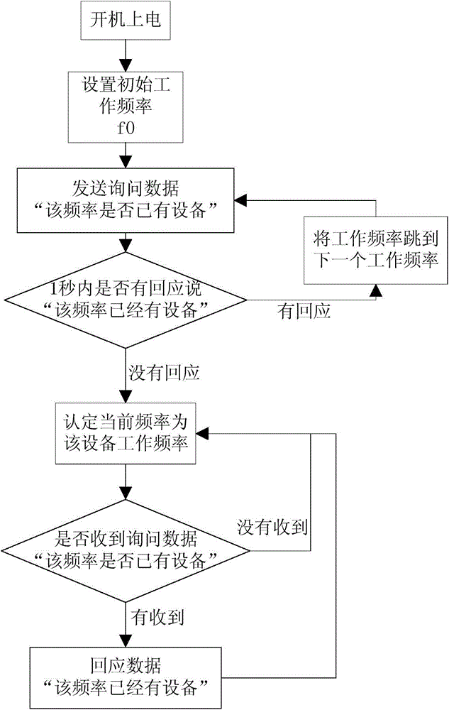
[0034] Such as figure 1 As shown in FIG. 1 , it is a schematic flowchart of realizing that each wireless transmitting terminal has a different working frequency from other wireless transmitting terminals through frequency hopping in Embodiment 1 of the present invention. Before performing frequency hopping, it is first necessary to power on all wireless transmitters, and set a power-on time difference between the wireless transmitters, that is, the wireless transmitters are powered on in a corresponding order. The minimum allowable difference in power-on time is 1 ms.

[0035] In addition, each wireless transmitter also presets an initial operating frequency f0, so that after all wireless transmitters are turned on, each wireless transmitter will work at the initial operating frequency f0, which is equivalent to completing the initialization of the wireless transmitter. process.

[0036] After the wireless transmitter completes the initialization, it starts a process of freq...

Embodiment 2

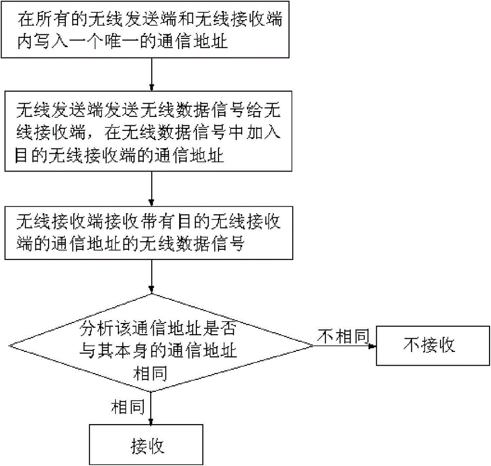
[0047] Such as figure 2 As shown, it is a schematic flow diagram of realizing that each wireless sending end has a communication address different from other wireless sending ends by adding a communication address in the wireless data signal in Embodiment 2 of the present invention. The specific flow is as follows:

[0048] First of all, write a unique communication address in all wireless transmitters and wireless receivers. Specifically, by adding a communication address in the communication protocol between wireless transmitters and wireless receivers, all wireless transmitters The wireless receiving end and the wireless receiving end have their own different communication addresses, and the communication between the wireless sending end and the wireless receiving end is unique;

[0049] Secondly, when each wireless transmitting terminal sends a wireless data signal to the wireless receiving terminal, the communication address of the destination wireless receiving terminal...


PUM


Abstract

The invention discloses a wireless frequency hopping scanning method which is used to realize that a wireless receiving end alternatively carries out one-to-one wireless communication with wireless sending ends. The method comprises the following steps that each wireless sending end selects only one working frequency for the wireless sending end itself through a frequency hopping mode; when receiving a wireless data signal sent by each wireless sending end, the wireless receiving end firstly scans working frequencies of all the wireless sending ends, alternatively selects one wireless sending end and receives the wireless data signal sent by the wireless sending end. Through a mode of writing only one communication address in each wireless sending end and the wireless receiving end, one-to-one communication between the wireless sending ends and the wireless receiving end is realized. By using the method of the invention, during a wireless communication process, phenomena of mutual signal interference, superposition or offset and the like are avoided; integrity and accuracy of data sending and receiving are guaranteed and communication flexibility between wireless equipment is increased.

Description

technical field [0001] The invention relates to the technical field of wireless communication, in particular to a wireless frequency hopping scanning method for realizing one-to-one communication between wireless communication devices by adopting frequency hopping or adding a communication address in a communication protocol. Background technique [0002] Wireless communication is a communication method that uses the characteristics that electromagnetic wave signals can propagate in free space for information exchange. With the continuous expansion of the scope of wireless communication applications, wireless communication technology has been applied to all aspects of our lives, such as wireless remote controls, walkie-talkies, logistics management, wireless meter reading, access control, etc. However, in the actual communication process, the data signal transmitted by the wireless communication equipment is often interfered by various factors. If it is not handled properly,...

Claims


Application Information

Patent Timeline
Patent Type & Authority Applications(China)
IPC IPC(8): H04W48/16H04B1/713
Inventor 姚玺峰
Owner NORTHWEST INSTR SHANGHAI
Why Eureka
Try Eureka