Wear-resistant layer and method for producing a wear-resistant layer
A technology of wear-resistant layer and filling material, which is applied in the field of wear-resistant layer and can solve problems such as expensive
- Summary
- Abstract
- Description
- Claims
- Application Information
AI Technical Summary
Problems solved by technology
Method used
Image

Examples
Embodiment 1
[0045] With the aid of thermal spraying, the wear layer is applied to the figure 1 on the leaves. With binder material NiCrSiB and filler material Al 2 o 3 -ZrO 2 Implementation basis Figures 1 to 4 the embodiment.
[0046] figure 1 A view is shown of a component front side 2 , in particular of a blade 1 , such as a turbine blade, which can be used for a turbine wheel of a turbocharger. On the front side of the turbine blade, ie the suction side 2 , an anti-wear layer is applied, which is also referred to as the front end layer. The rear side 3 of the turbine blade, ie the pressure side, is not shown in this figure. The suction side 2 and the pressure side 3 are delimited from the outside by blade tips 6 . The blade tip 6 forms the leading edge 4 with the suction side 2 . The suction side 2 is delimited by an inlet side 7 , an outlet side 8 , blade tips 6 and blade bottoms 5 . In the operating state, a compressible, in particular gaseous, fluid flows along the sucti...
Embodiment 2
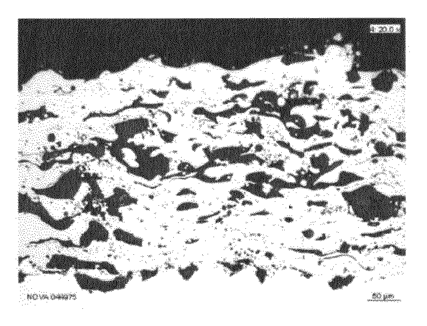
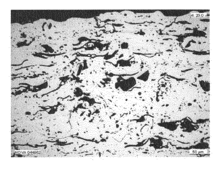
[0053] For this example, Ni-15Cr-5Si-4B with a particle size of -63 + 16 μm was used. This fine-grained material is preferred since it must be melted in a single process step. This powder with the selected composition is a self-flowing material which, when melted, simultaneously allows metallic bonding to the base material of the substrate and does not exhibit a lamellar structure that could favor crack propagation. The Vickers hardness HV0.3 of the adhesive material measured in the metal matrix after the thermal spraying process had an average value of 747 HV0.1. This hardness is 1.8 times greater than the hardness value achievable by means of laser coating welding.
[0054] Use Al 2 o 3 with ZrO 2 or just use Al 2 o 3 as filling material. The particles are usually produced by melting them together and then comminuting, so that the surface has sharp edges. Confirmed, Al 2 o 3 with ZrO 2 layer used as filler material, compared to only Al 2 o 3 For the layer used a...
PUM
| Property | Measurement | Unit |
|---|---|---|
| Vickers hardness | aaaaa | aaaaa |
Abstract
Description
Claims
Application Information
 - R&D
- Intellectual Property
- Life Sciences
- Materials
- Tech Scout
- Unparalleled Data Quality
- Higher Quality Content
- 60% Fewer Hallucinations
Browse by: Latest US Patents, China's latest patents, Technical Efficacy Thesaurus, Application Domain, Technology Topic, Popular Technical Reports.
© 2025 PatSnap. All rights reserved.Legal|Privacy policy|Modern Slavery Act Transparency Statement|Sitemap|About US| Contact US: help@patsnap.com