A push-type topping machine that can collect cotton buds

A topping machine and budding technology, applied to agricultural machinery and tools, cutting tools, cutting equipment, etc., can solve the problems of rolling, easily delaying farming time, and affecting popularization and application, so as to reduce the radius of gyration, improve adaptability, Ensure consistent effect

Inactive Publication Date: 2017-11-21
SHANDONG UNIV OF TECH
View PDF5 Cites 0 Cited by
  • Summary
  • Abstract
  • Description
  • Claims
  • Application Information

AI Technical Summary

Problems solved by technology

[0002] Cotton topping is one of the key technologies to ensure the yield and quality of cotton. However, since the topping process must find the top buds of cotton, manual work is often used, which is not only labor-intensive and time-consuming, but also easily delays the farming time; and for the existing cotton As for the topping machine, because the topping cutters all use disc-type topping knives, the top buds can not be collected, which is not conducive to the control of diseases and insect pests; the distance between the topping knives cannot be adjusted, and it is difficult to meet the technical requirements of different planting agronomy; When tractors are used as power, the chassis and tires are easy to scratch, pull, and crush cotton plants, which seriously affects the popularization and application of this technology.

Method used


Image

  • A push-type topping machine that can collect cotton buds
  • A push-type topping machine that can collect cotton buds
  • A push-type topping machine that can collect cotton buds

Examples


Embodiment Construction

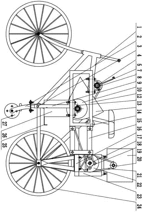
[0023] in figure 1 In this, first fix the rear frame 23 on the rear seat 16 of the bicycle 1, fix the engine 19 on the rear frame 23, and ensure that the engine 19 is located directly above the rear seat 16 of the bicycle 1, and then fix the support wheels 24 on On the long slot 6 of the rear frame 23; ensure that the rear frame 23 is in a horizontal state. The profiling wheel 27 is inserted into the front frame supporting square tube 8 through the profiling wheel column 2 and locked with a fastening screw 3; then the front frame 10 and the rear frame 23 are connected with a four-bar profiling frame 15; The auger 9 is fixed on the lower side of the rectangular front frame 10 with a bearing seat 12, and the auger bottom groove 13 is fixed on the front frame 10; the cutter shaft 4 is fixed on the upper side of the front frame 10 with a bearing seat 12.

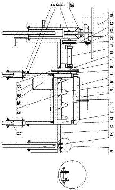
[0024] in figure 2 In the middle, the top cutter assembly 5 is threaded on the cutter shaft 4 and locked with the positioning sc...


PUM


Abstract

The invention provides a thrust type cotton top-cutting machine with apical buds of cotton capable of being collected. The cotton top-cutting machine comprises a bicycle, an engine, a cutter shaft, a top-cutting device assembly, an auger, a rear rack, a supporting wheel, a four-bar profile frame, an auger bottom groove, a rear seat, a front rack, an intermediate shaft, an apical bud collecting box, contour wheels and the like. The thrust type cotton top-cutting machine is characterized in that the rear rack is fixed to the rear seat of the bicycle, the engine is fixed to the left side of the rear rack, and the supporting wheel is installed on the right side of the rear rack through a long slotted hole; the front rack is connected with the middle of the rear rack through the four-bar profile frame; the cutter shaft with the top-cutting device assembly is installed on the upper edge of the rectangular front rack through a bearing pedestal, and the auger is installed on the lower edge of the front rack; the apical bud collecting box is installed on the lower left portion of the auger bottom groove; the intermediate shaft is installed on the side close to the engine, a power input wheel is installed on the left side of the intermediate shaft, and an outer side belt wheel is installed on the right side of the intermediate shaft. According to the thrust type cotton top-cutting machine, the top-cutting heights and the line spacing can be adjusted, and thus the operation adaptability of machines and tools is improved; the four-bar profile frame is adopted, and therefore the consistency of the top-cutting heights is guaranteed.

Description

Technical field [0001] The invention relates to a thrust type topping machine capable of collecting cotton and belongs to the field of agricultural machinery and equipment. Background technique [0002] Cotton topping is one of the key technologies to ensure the yield and quality of cotton. However, since the top buds of cotton must be found during the topping process, manual operations are often used, which not only consumes labor and time, but also easily delays agricultural time. For existing cotton For the topping machine, since the topping device adopts a disc topping knife, the top buds cannot be collected, which is not conducive to the control of diseases and insect pests; the topping knife distance cannot be adjusted, and it is difficult to meet the technical requirements of different planting agronomy; When a tractor is used as power, the chassis and tires are easy to scratch, pull, and crush cotton plants, which seriously affect the popularization and application of thi...

Claims


Application Information

Patent Timeline
Patent Type & Authority Patents(China)
IPC IPC(8): A01G3/08A01G7/06
CPCA01G3/08A01G7/06
Inventor 耿端阳孟鹏祥孙久坤李宝胜李玉环刘俊麟
Owner SHANDONG UNIV OF TECH
Why Eureka
Try Eureka