
Beverage faucet

A technology for beverages and faucets, applied in beverage preparation devices, household appliances, applications, etc., can solve the problems of difficulty in cleaning, good heating and disinfection effect, and inability to drink, so as to ensure quality and preservation time, soften and improve taste, and improve effect of taste

Inactive Publication Date: 2015-11-11
ADT CHINA LTD
View PDF10 Cites 0 Cited by
  • Summary
  • Abstract
  • Description
  • Claims
  • Application Information

AI Technical Summary

Problems solved by technology

[0002] Beverages such as beer and soda are usually stored in containers and pipelines. When drinking is needed, the beverage is released for drinking by opening the beverage faucet; beverage faucets usually work in public places, and public places usually have a lot of bacteria due to the large number of people. Living microorganisms, some of these living organisms survive at the port of the beverage faucet. When the beverage faucet is opened, because the microorganisms are living organisms, a small amount of microorganisms will enter the pipeline that transports the beverage against the flow direction of the beverage, and finally enter the container where the beverage is stored However, a large number of reproductions will form harmful microbial films, which not only affects the hygienic status of beverages, but also makes the beverages quickly deteriorate and cannot be drunk, and it is difficult to eliminate them in the later stage of cleaning. Therefore, the beverages need to be disinfected. The existing disinfection technology uses ultraviolet disinfection. , heat disinfection, or alcohol disinfection, etc., the penetration energy of ultraviolet rays is weak, and it is not easy to completely remove the microorganisms in the beverage faucet, especially for beverages with complex ingredients. Disinfection is not easy to have an effect on the microorganisms in the beverage faucet, and it is easy to leave bad smell in the beverage

Method used


Image

  • Beverage faucet
  • Beverage faucet
  • Beverage faucet

Examples


Embodiment Construction

[0017] A specific embodiment of the present invention will be described in detail below in conjunction with the accompanying drawings, but it should be understood that the protection scope of the present invention is not limited by the specific embodiment.

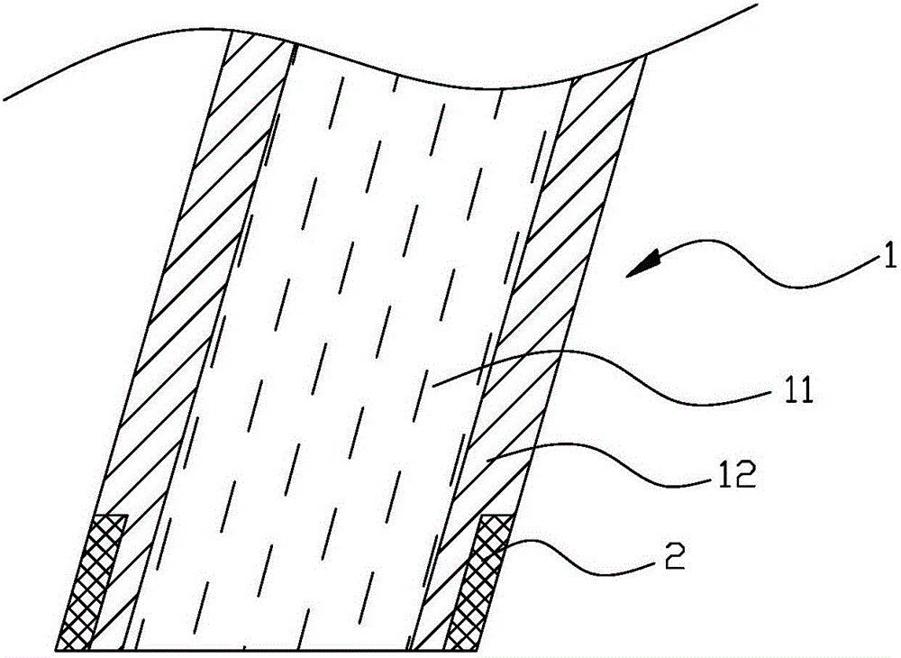
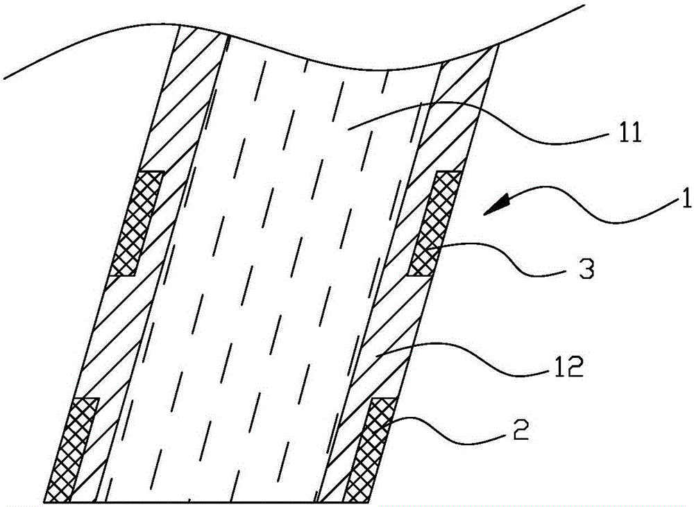
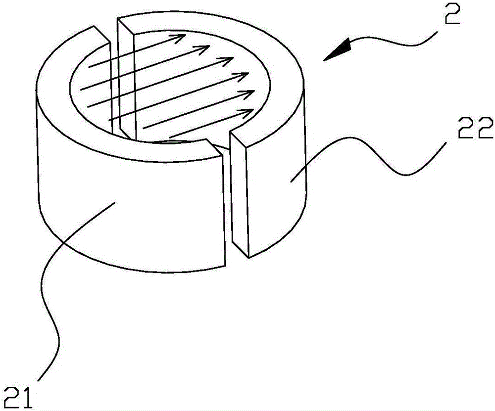
[0018] A kind of beverage faucet of the present invention is placed such as figure 1 , 2 , 3, including the fluid channel 11 in the beverage faucet 1, the beverage flows out through the fluid channel 11 for external drinking; wherein a magnet 2 is set in the fluid channel 11, and the magnet 2 is a group of magnets, including N poles 21 and S poles of the magnets. The pole 22, the magnet 2 surrounds the fluid channel 11 embedded in the beverage faucet, the magnetic field line generated by the magnet passes through the section of the fluid channel from the N pole 21 to the S pole 22, the beverage in the fluid channel usually contains electrolyte, and the beverage forms a conductor in the flow channel Therefore, when the bev...


PUM


Abstract

The invention discloses a beverage faucet. The beverage faucet comprises a liquid passage, wherein a magnet is arranged in the liquid passage, magnetic lines of force generated by the magnet pass through a section of the liquid passage, a beverage in the liquid passage generally contains electrolyte so as to form a conductor in the liquid passage, therefore, the beverage generates voltage when passing through the magnetic lines of force, living body microorganisms at the opening of the beverage faucet can be shocked when passing through a region with voltage towards direction opposite to that of the beverage, so that shock of the living body microorganisms is caused. The living body microorganisms suffering from shock have no capacity for action, so as to be driven out of the liquid passage by the following-up flowing beverage, therefore, the beverage in the beverage faucet is not polluted by the microorganisms, and is guaranteed to be clean all the time, and meanwhile, the magnetic lines of force also can achieve the effects of softening the water molecules in the beverage and improving the mouth taste.

Description

technical field [0001] The invention relates to a beverage drinking device, in particular to a beverage faucet. Background technique [0002] Beverages such as beer and soda are usually stored in containers and pipelines. When drinking is needed, the beverage is released for drinking by opening the beverage faucet; beverage faucets usually work in public places, and public places usually have a lot of bacteria due to the large number of people. Living microorganisms, some of these living organisms survive at the port of the beverage faucet. When the beverage faucet is opened, because the microorganisms are living organisms, a small amount of microorganisms will enter the pipeline that transports the beverage against the flow direction of the beverage, and finally enter the container where the beverage is stored However, a large number of reproductions will form harmful microbial films, which not only affects the hygienic status of beverages, but also makes the beverages quic...

Claims


Application Information

Patent Timeline
Patent Type & Authority Applications(China)
IPC IPC(8): A47J31/46
Inventor 麦克斯·塔哈
Owner ADT CHINA LTD
Learn More