High-effective gas-water separator

A gas-water separator and high-efficiency technology, applied in separation methods, dispersed particle separation, chemical instruments and methods, etc., can solve the problems of energy consumption and waste, high power consumption, etc., and achieve reliable performance, simple structure, high efficiency and stable gas-water The effect of separation efficiency

Active Publication Date: 2015-11-11
HONGRIJIA DEPURATE FACILITY SCI & TECH CO LTD
View PDF4 Cites 1 Cited by
  • Summary
  • Abstract
  • Description
  • Claims
  • Application Information

AI Technical Summary

Problems solved by technology

The overall operation of the equipment requires a large amount of electricity
Serious waste of energy consumption

Method used


Image

  • High-effective gas-water separator
  • High-effective gas-water separator
  • High-effective gas-water separator

Examples


Embodiment Construction

[0034] The above and other technical features and advantages of the present invention will be described in more detail below with reference to the accompanying drawings and embodiments.

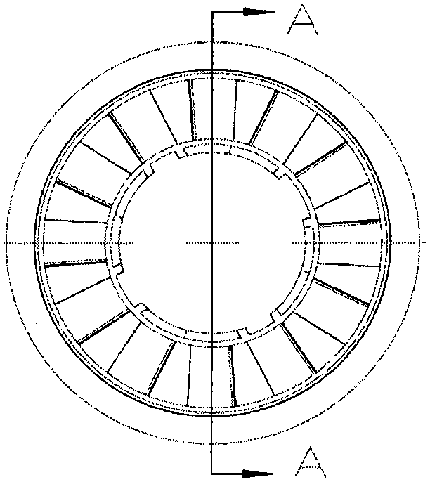
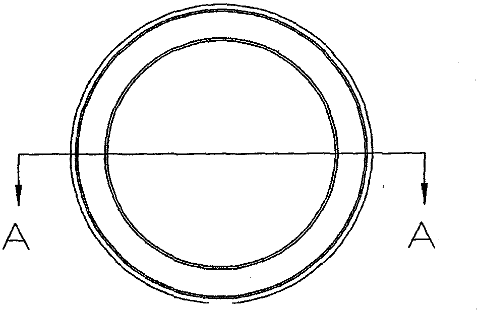
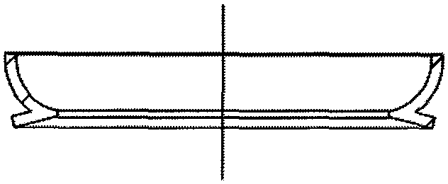
[0035] High-efficiency gas-water separator of the present invention such as Figure 1-Figure 11 As shown, it includes the guide part 2, the cross section of the guide part 2 is a trumpet-shaped structure, the upper port of the guide part 2 is sealed and connected with the inner tube of the pipe head 6 through a sealed connection, and the middle part is provided with a secondary separation guide groove assembly position The lower port is designed with an inner circle and an outer groove cylinder; the water mist and oil mist collector 4 is installed on the secondary separation diversion groove 3 to form a sealing groove and realize a low flow rate separation device; The separation diversion groove 3 is further designed with an interception and condensation groove to form a secondary collection ...


PUM


Abstract

The invention provides a high-effective gas-water separator, which includes a tube head, a tube body, a flow guide part, a secondary separation flow guide trough, a water fog and oil fog collector, and an air oriented flow guide device. The tube head includes a tube body connection port and a flow guide connection port arranged on the lower end of the tube head, a gas inlet arranged on the front end of the tube head, and a gas outlet arranged on the back end. The flow guide connection port is connected to the upper part of the flow guide part. An assembling position of the secondary separation flow guide trough is disposed in the middle of the flow guide part. A circular cylinder, of which the interior is circular and the exterior is trough-like in shape, is designed at the lower end port. The secondary separation flow guide trough is connected to the middle part of the flow guide part through the assembling position of the secondary separation flow guide trough in a sleeving manner. The water fog and oil fog collector and the air oriented flow guide device successively sleeve the flow guide part and are arranged above the secondary separation flow guide trough. The inner wall of the tube body sleeves the circular cylinder, of which the interior is circular and the exterior is trough-like in shape, of the flow guide part; and the outer wall of the tube body is arranged through the flow guide part and the secondary separation flow guide sleeving the flow guide part. The water fog and oil fog collector and the air oriented flow guide device are then connected to the tube body connection port at the lower part of the tube head.

Description

technical field [0001] The invention relates to a gas-water separator, in particular to a high-efficiency gas-water separator with extremely high requirements on the quality of gas used in terminal equipment. Background technique [0002] Compressed air is the second largest power energy after electricity, and it is also a process gas source with multiple uses. Its application range covers environmental protection, automobile manufacturing, petroleum, chemical industry, metallurgy, electric power, machinery, light industry, textile, electronics , food, medicine, biochemistry, national defense, scientific research and other industries and departments. [0003] As we all know, the source of compressed air comes from the atmosphere, and the atmosphere contains quite a lot of impurities, mainly: solid particles - about 140 million particles per cubic meter in the atmospheric environment, about 80% of which are smaller than 2μm, the air compressor filter is unable to eliminate i...

Claims


Application Information

Patent Timeline
IPC IPC(8): B01D45/16B01D45/02
Inventor 刘柏藩李雪琴
Owner HONGRIJIA DEPURATE FACILITY SCI & TECH CO LTD
Why Eureka
Try Eureka