Al technical title is built by PatSnap Al team. It summarizes the technical point description of the patent document.
A rubber-plastic pipe and edge trimming technology, applied in metal processing and other directions, can solve the problems of work-related injury risks, time-consuming and labor-intensive, and low work efficiency, and achieve the effects of reducing work-related injury risks, reducing labor intensity, and improving production efficiency.
Inactive Publication Date: 2015-11-11
SHENZHEN WOER HEAT SHRINKABLE MATERIAL +4
View PDF5 Cites 0 Cited by
Summary
Abstract
Description
Claims
Application Information
AI Technical Summary
This helps you quickly interpret patents by identifying the three key elements:
Problems solved by technology
Method used
Benefits of technology
Problems solved by technology
Such equipment and operations are not only time-consuming, labor-intensive, and inefficient, but also pose a risk of work-related injuries
Method used
Image
Click on the blue label to locate the original text in one second.
Reading with bidirectional positioning of images and text.
Examples
Embodiment Construction
[0035] In order to describe in detail the technical content, structural features, goals and effects achieved by the device for removing trimmings from rubber and plastic pipes of the present invention, the following will be further described in conjunction with the embodiments and accompanying drawings.
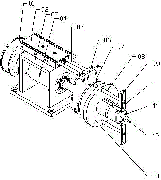
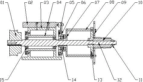
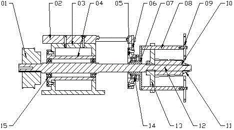
[0036] like Figure 1 to Figure 4 As shown, an embodiment of a rubber and plastic pipe trimming removal device is disclosed. The present invention includes a synchronous wheel 01, a double-axis cylinder 02, a seat frame 03, a bearing seat 04, a mobile bearing seat 05, a push plate 06, and a push plate 07 , push rod 08, push finger 09, support mold 10, lock nut 11, driving shaft 12, support plate 13, bearing A14 and bearing B15, because the control system selects commercially available PLC controller standard components and does not need to be shown in the accompanying drawings It shows that the synchronous wheel 01 is set on one end of the driving shaft 12 and fixed with a ke...
PUM
Abstract
The invention discloses a rubber tube scrap edge unloading device. The rubber tube scrap edge unloading device comprises a synchronizing wheel, an air cylinder, a seat frame, a bearing base, a movable bearing base, a pushing plate, a pushing disc, a pushing rod, a pushing finger, a supporting mould, a locking nut, a drive shaft, a supporting disc, a bearing A, a bearing B and a control system. The synchronizing wheel is arranged at one end of the drive shaft in a sleeving mode; the bearing B is arranged on the waist part of the drive shaft in the sleeving mode; the bearing base and a double-shaft air cylinder are fixed on the seat frame; the pushing disc is arranged on the waist of the drive shaft in the sleeving mode, adjacent to the seat frame, and connected with the movable bearing base; the movable bearing base is connected with the piston rod of the air cylinder; the pushing rod penetrates through a through hole in the supporting disc, and then is connected with the pushing finger; the supporting disc and the supporting mould are arranged at the other end of the drive shaft in the sleeving mode, and are fastened by nuts; and the pushing disc, the supporting disc and the supporting mould are driven by the drive shaft to rotate. According to the rubber tube scrap edge unloading device, scrap edges of the rubber tubes can be automatically unloaded, the labor intensity is relieved, the industrial injury risks are reduced, and the production efficiency is improved.
Description
technical field [0001] The invention belongs to the manufacturing field of automatic section cutting equipment for rubber and plastic pipes, and in particular relates to a device for removing trimmings of rubber and plastic pipes. Background technique [0002] In the rubber and plastic tube production industry, especially in the segmental expansion process of the heat shrinkable tube industry, since the two ends of the embryonic tube are not flat after expansion, it is necessary to cut off a part of the edge material at both ends of the tube with a lathe, and the remaining edge material in this process It will be tightly hooped on the support mold, and it is necessary to manually remove the edge material by hand, so that another tube can be inserted into the support mold to continue cutting. Such equipment and operation actions are not only time-consuming and labor-intensive, but also inefficient, and there is a risk of work-related injuries. [0003] Therefore, be necessar...
Claims
Application Information
Patent Timeline
Application Date:The date an application was filed.
Publication Date:The date a patent or application was officially published.
First Publication Date:The earliest publication date of a patent with the same application number.
Issue Date:Publication date of the patent grant document.
PCT Entry Date:The Entry date of PCT National Phase.
Estimated Expiry Date:The statutory expiry date of a patent right according to the Patent Law, and it is the longest term of protection that the patent right can achieve without the termination of the patent right due to other reasons(Term extension factor has been taken into account ).
Invalid Date:Actual expiry date is based on effective date or publication date of legal transaction data of invalid patent.