Al technical title is built by PatSnap Al team. It summarizes the technical point description of the patent document.
A technology of micro-foaming and dehydration device, which is applied in the field of mechanical equipment, can solve the problems of product deformation, large internal stress, failure to achieve quality, etc., and achieves the effect of no internal stress, efficient mixing, and not easy to deform
Active Publication Date: 2015-11-11
ZHEJIANG JIACHENG MACHINERY
View PDF3 Cites 4 Cited by
Summary
Abstract
Description
Claims
Application Information
AI Technical Summary
This helps you quickly interpret patents by identifying the three key elements:
Problems solved by technology
Method used
Benefits of technology
Problems solved by technology
[0002] The plastic product industry is the pillar industry of my country's light industry. The structure of plastic parts is becoming more and more complex, and the industrial requirements for the size of the products are also getting higher and higher. Traditional injection molding manufacturing devices are used to produce these parts, and there are relatively large inner parts in the products. Stress, uneven shrinkage will lead to product deformation, so as not to meet the required quality
Method used
Image
Click on the blue label to locate the original text in one second.
Reading with bidirectional positioning of images and text.
Examples
Embodiment Construction
[0012] The present invention will be further described below in conjunction with the accompanying drawings and embodiments.
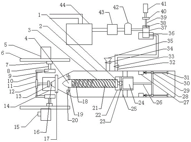
[0013]An injection micro-foaming device of the present invention comprises a bearing 1, a barrel 2, a screw 3, a screw head 4, a frame 5, a linear motor 6, a moving block 7, a first rod 8, a first cylinder 9, a second rod Rod 10, first push plate 11, first push rod 12, first pressure plate 13, cover body 14, controller 15, nozzle 16, rubber ring 17, left tooth lead 18, check ring 19, washer 20, right Tooth lead 21, casing 22, leak-proof ring 23, first motor 24, stop ring 25, connecting rod 26, second motor 27, bracket 28, screw nut 29, lead screw 30, bearing frame 31, intake pipe 32. Intake valve 33, feed valve 34, feed port 35, condensation water device 36, compression tank 37, second pressure plate 38, second push rod 39, second push plate 40, second cylinder 41, desulfurization device 42. Dehydration device 43 and gas storage tank 44, the gas storag...
PUM
Abstract
The invention discloses an injection micro-foaming device, and belongs to the technical field of machine equipment. The injection micro-foaming device comprises a bearing, a material barrel, a screw, a screw head, a frame, a linear motor, a movable block, a first supporting rod, a first air cylinder, a second supporting rod, a first push plate, a first push rod, a first press plate, a housing body, a controller, a spraying nozzle, a rubber ring, a leftward-thread lead section, a non-return valve, a gasket, a rightward-thread lead section, a machine shell, an anti-leaking ring, a first motor, a flow stop ring, a connecting rod, a second motor, a support, a nut, a lead screw, a bearing frame, an air inlet pipe, an air inlet valve, a feeding valve, a feeding inlet, a condensate water device, a compression tank, a second press plate, a second push rod, a second push plate, a second air cylinder, a desulfurizer, a dehydration device and an air storage tank. The air storage tank is connected with a smoke exhausting system of a factory through a pipeline and connected with the dehydration device through a pipeline. The injection micro-foaming device has the advantages of achieving efficient mixing, eliminating internal stress of injection products and preventing products from being prone to deformation.
Description
technical field [0001] The invention relates to an injection microfoaming device, which belongs to the technical field of mechanical equipment. Background technique [0002] The plastic product industry is the pillar industry of my country's light industry. The structure of plastic parts is becoming more and more complex, and the industrial requirements for the size of the products are also getting higher and higher. Traditional injection molding manufacturing devices are used to produce these parts, and there are relatively large inner parts in the products. Stress, uneven shrinkage will lead to product deformation, so that the required quality cannot be achieved. In order to solve the above difficulties, it is necessary to develop an injection micro-foaming device that can make the injection molded product have no stress inside and make the product less prone to deformation. Contents of the invention [0003] The object of the present invention is to provide an injection...
Claims
Application Information
Patent Timeline
Application Date:The date an application was filed.
Publication Date:The date a patent or application was officially published.
First Publication Date:The earliest publication date of a patent with the same application number.
Issue Date:Publication date of the patent grant document.
PCT Entry Date:The Entry date of PCT National Phase.
Estimated Expiry Date:The statutory expiry date of a patent right according to the Patent Law, and it is the longest term of protection that the patent right can achieve without the termination of the patent right due to other reasons(Term extension factor has been taken into account ).
Invalid Date:Actual expiry date is based on effective date or publication date of legal transaction data of invalid patent.