
An air-feather airflow directional aircraft

A technology of aircraft and wings, which is applied in the field of air-feather airflow directional aircraft, and can solve problems such as the complexity of the transmission system

Active Publication Date: 2017-03-15
孙炳岐
View PDF12 Cites 0 Cited by
  • Summary
  • Abstract
  • Description
  • Claims
  • Application Information

AI Technical Summary

Problems solved by technology

[0006] Since the flapping-wing aircraft flies according to the principle that a pair of wings beat the air to generate lift and change the flapping angle of the wings to generate propulsion when a bird is flying, so the flapping-wing aircraft also needs a pair of wings to sail safely, but the flapping wings make The transmission system is too complicated, and the wings need to have a large enough area, and the large wing area will make the flight and take-off and landing be restricted by the surrounding environment, and its use has certain limitations.

Method used


Image

  • An air-feather airflow directional aircraft
  • An air-feather airflow directional aircraft
  • An air-feather airflow directional aircraft

Examples


Embodiment Construction

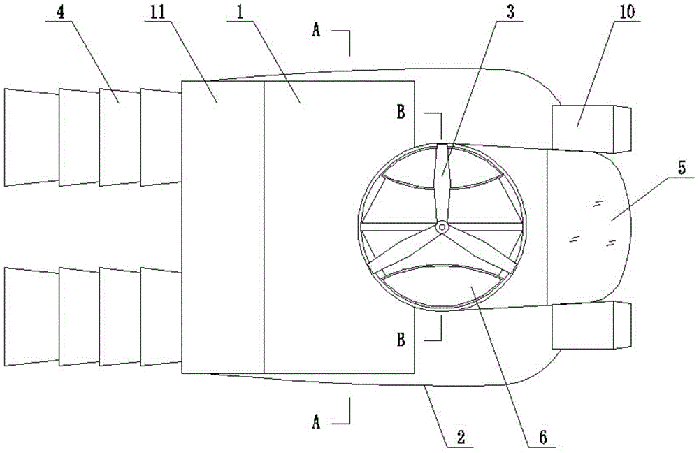
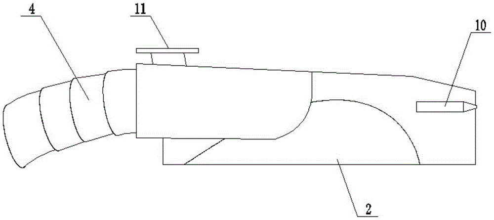
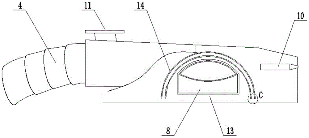
[0033] refer to Figure 1 to Figure 6, the air-wing type airflow directional aircraft includes a body 1, a control room 5, a lifting system and a propulsion system, the lifting system includes a wing-shaped wing 2, a lifting duct 6 and a propeller 3, and the control room 5 is located at The front part of the body 1 is provided with a central control system, a power transmission system, various monitoring instruments and a satellite positioning system, etc., the lifting duct 6 is located in the middle of the body 1, and the propeller 3 is located in the lifting duct 6 Inside, the lifting duct 6 is located below the propeller 3 and is provided with a herringbone-shaped air compartment plate 7 in the longitudinal section. connection, the shock absorber is connected with the piston engine or turboshaft engine located in the control room 5, the propeller 3 is a coaxial reverse propeller, and the side walls of the left and right sides of the lifting duct 6 are symmetrically provided...


PUM


Abstract

A gas wing airflow directional aircraft comprises a machine body and a control room and is characterized in that the control room is arranged at the front part of the machine body, a lifting duct is arranged in the middle of the machine body, a propeller is arranged in the lifting duct, a gas separation bin plate with a herringbone longitudinal section is arranged below the propeller in the lifting duct, a transmission shaft of the propeller penetrates through a central hole of the air separation bin plate and is connected with a power transmission system in the control room, gas spraying windows are symmetrically formed in side walls of left and right sides of the lifting duct, the bottom end of the air separation bin plate is connected with the gas separation bin plate, wing-shaped airfoils are symmetrically arranged at the parts, outside the gas spraying windows, at the side walls of left and right sides of the lifting duct; the sections of the airfoils are outwards bulged arc surfaces; rear half parts, close to the machine body, of a propelling duct are symmetrically arranged at two sides of the machine body, and the rear part is connected with a propelling spraying tube, and a fan is arranged in the propelling duct. The gas wing airflow directional aircraft can form directional airflows, the airflows flow to the inside of the airfoils, and are then sprayed out from the bottom ends of the airfoils to form counter-acting force to the machine body so as to fast support the machine body.

Description

[0001] Technical field: [0002] The invention relates to an aircraft, in particular to an air-feather airflow directional aircraft. [0003] Background technique: [0004] As the name suggests, the aircraft is to fly away from solid land and soar in the vast sky to come and go freely. The most important thing to fly is to take off smoothly and land safely. From watching birds flying in the blue sky to now being able to travel by plane, there are countless pioneers who have studied the aviation industry. Since Ford proposed the concept of flying cars for nearly 100 years, many inventors believe that the future personal transportation It will definitely develop in the direction of flying cars. Although it is not difficult to fly a car into the sky with the current science and technology, it is very difficult to do it when there are cars on all sides of the crowded road, and it is even more difficult. The most important thing is to let the car take off smoothly without being aff...

Claims


Application Information

Patent Timeline
Patent Type & Authority Patents(China)
IPC IPC(8): B64D27/16
Inventor 孙炳岐
Owner 孙炳岐
Learn More