
A honeycomb fiber filter

A fiber filter and honeycomb technology, which is applied in the field of honeycomb fiber filters, can solve the problems that the sewage interception capacity cannot be fully utilized, the variable porosity cannot be realized, and the water head loss is large, so as to protect normal operation and service life, reduce The effect of backwash water volume and long working cycle

Inactive Publication Date: 2017-05-24
金光斌
View PDF5 Cites 0 Cited by
  • Summary
  • Abstract
  • Description
  • Claims
  • Application Information

AI Technical Summary

Problems solved by technology

The above-mentioned filter overcomes some deficiencies of the capsule squeeze filter, but sometimes the pressure plate is prone to jamming, and the fiber filter will no longer run like a fixed curved track after a long period of operation. It bends slowly at the beginning of operation, but directly bends according to the curved track, and it is in place at one time, and the porosity cannot be changed during the filtration process, which will cause a large loss of water head, and the sewage interception capacity cannot be fully utilized.

Method used


Image

  • A honeycomb fiber filter
  • A honeycomb fiber filter
  • A honeycomb fiber filter

Examples


Embodiment Construction

[0013] The present invention will be further described below in conjunction with the accompanying drawings.

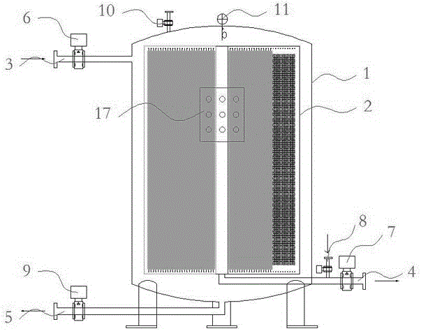
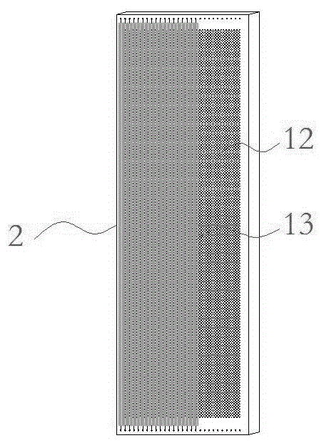
[0014] The honeycomb fiber filter of the present invention is composed of a cylinder body (1), a honeycomb porous plate radially installed in the cylinder, and a filter core device vertically hanging on the surface of the honeycomb porous plate.

[0015] Cylinder (1) and water inflow pipe (3) and inflow control valve (6), filtered water discharge pipe (4) and discharge control valve (7), air flow control valve on the compressed air inflow pipe (8) It is connected with the discharge valve (10) on the compressed air discharge pipe, as well as the backwash water discharge pipe (5) and the backwash water discharge control valve (9); a pressure sensor (11) is installed on the upper end of the filter to sense The pressure inside the cylinder (1); the front of the cylinder (1) is equipped with a control panel, and the user can manually adjust the water filtration or backwashi...


PUM


Abstract

The invention relates to a filter, in particular to a honeycomb fiber filter which is composed of a main body, honeycomb type porous plates installed in the main body in a radial mode and a fiber filter core device vertically hung at the position of the face of the honeycomb type porous plate. The main body is connected with a water body inflow pipe, an inflow amount control valve, a filtering water discharging pipe, a discharge amount control valve, an air flow control valve positioned on a compressed air inflow pipe, a drain valve positioned on a compressed air discharge pipe, a backwash water discharge pipe and a backwash water discharge amount control valve. A pressure sensor is arranged at the upper end of the filter, the filtering area is increased, the filtering precision is improved, and the backwash effect is good.

Description

technical field [0001] The invention relates to a filter, in particular to a honeycomb fiber filter. Background technique [0002] In the current fiber filter, the fiber bundles are vertically arranged up and down in the container, and one end of the fiber bundles is tied to a porous fixed plate, and the other end is tied to a porous movable plate or other movable supporting devices. When filtering, the porous movable plate or the movable supporting device moves towards the direction of the porous fixed plate, compressing the fiber bundles to form a filter layer, and the filtering direction is upflow, downflow or double flow. During backwashing, the compressed fiber bundles are stretched to achieve thorough cleaning of the fiber layer. The above-mentioned filter overcomes some deficiencies of the capsule squeeze filter, but sometimes the pressure plate is prone to jamming, and the fiber filter will no longer run like a fixed curved track after a long period of operation. I...

Claims


Application Information

Patent Timeline
Patent Type & Authority Patents(China)
IPC IPC(8): B01D24/10B01D24/46C02F1/44B01D63/00B01D65/02
Inventor 金光斌金桂花
Owner 金光斌
Learn More