
Glass production wastewater treatment apparatus

A technology for producing wastewater and treatment devices, which is applied in ceramic wastewater treatment, water/sewage multi-stage treatment, water/sludge/sewage treatment, etc. And other issues

Inactive Publication Date: 2015-11-11
ZHEJIANG OCEAN UNIV
View PDF3 Cites 16 Cited by
  • Summary
  • Abstract
  • Description
  • Claims
  • Application Information

AI Technical Summary

Problems solved by technology

[0003] The first purpose of the present invention is to provide a glass production wastewater treatment device that is convenient for installing the press control box, which solves the problem of inconvenient installation of the press and the control box in the existing glass production wastewater treatment device
[0004] The second object of the present invention aims at further providing a glass production wastewater treatment device capable of preventing mice from climbing into the control box of the press on the basis of the first purpose, which solves the problem of the press control of the existing glass production wastewater treatment device The box is not rodent-proof

Method used


Image

  • Glass production wastewater treatment apparatus
  • Glass production wastewater treatment apparatus
  • Glass production wastewater treatment apparatus

Examples


Embodiment 2

[0042] Embodiment two, the difference with embodiment one is:

[0043] see Figure 4 , The lower end of the filter press control box 1 is provided with a supporting foot 11. The fixing structure 7 is disposed on the supporting foot 11 . The filter press control box 1 is a quadrilateral column. The front, rear, left, and right sides of the filter press control box 1 are all provided with connection holes 13 . An insect-proof plate 14 is connected to the connecting hole 13 . The lower end of the insect-proof board 14 is connected with a raised board 15 . Connecting ears 141 are provided at both horizontal ends of the lower end of the insect-proof plate 14 . Both ends of the heightening plate 15 in the horizontal direction are provided with hinge shafts 151 . The hinge shaft 151 is rotatably connected in the connecting ear 141 to hinge the heightening plate 15 and the insect-proof plate 14 together.

[0044] see Figure 5 , the upper end of the heightening plate 15 is inc...

Embodiment 3

[0068] Embodiment three, the difference with embodiment two is:

[0069] see Figure 14 , the rotating shaft 51 is pierced with a circular inner rod 511 . The inner rod 511 is a tubular structure. The inner surface of the rotating shaft 51 is provided with an inner friction layer 512 . The inner rod 511 includes a left rod 5111 and a right rod 5112 . The outer peripheral surfaces of the left rod 5111 and the right rod 5112 are provided with an outer friction layer 5113 . The outer friction layer 5113 covers the inner rod 511 along the circumference of the inner rod 511 . The left end of the left rod 5111 is connected with the rotating shaft 51 through the left energy-absorbing spring 513 . The right end surface of the left rod 5111 is provided with a plurality of first reversing teeth 5114 distributed along the circumferential direction of the left rod. The right end of the right rod 5112 is connected with the rotating shaft 51 through the right energy-absorbing spring 5...


PUM


Abstract

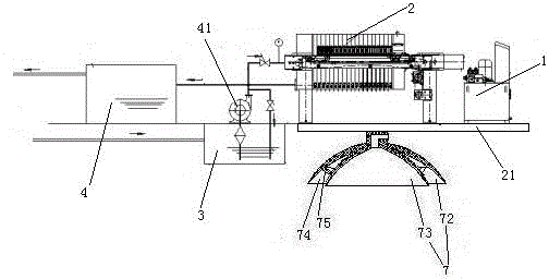
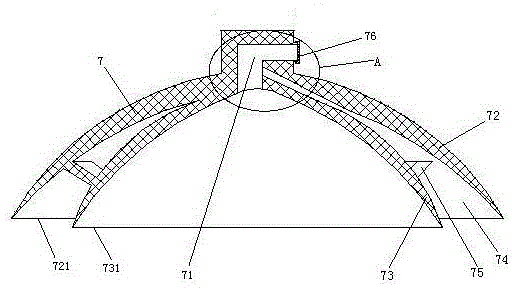
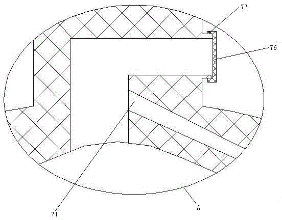
The present invention relates to a wastewater treatment apparatus, particularly to a glass production wastewater treatment apparatus, which comprises a press filter, a press filter control box, a wastewater pool, a sewage pump for conveying water in the wastewater pool to the press filter, a substrate and a filtrate collecting pool connected with the water outlet of the press filter, wherein the press filter and the press filter control box are connected on the substrate, the substrate is provided with a fixed structure, the fixed structure comprises a first suction disk, a second suction disk is arranged inside the first suction disk, and an adsorption groove is enclosed between the first suction disk and the second suction disk. The present invention provides the glass production wastewater treatment apparatus capable of conveniently installing the pressure machine control box, such that the problem that the pressure machine and the control box are inconveniently installed in the existing wastewater treatment apparatus is solved.

Description

technical field [0001] The invention relates to a waste water treatment device, in particular to a glass production waste water treatment device. Background technique [0002] In order to save water consumption during glass production, glass production wastewater needs to be treated to achieve recycling, and glass production wastewater is treated through corresponding glass production wastewater treatment devices. In the patent literature with the Chinese patent number ZL2009203180176, the authorized announcement number CN1201620047U, the authorized announcement date being November 3, 2010, and the patent document titled "A Circulation Device for Glass Cutting Wastewater", a glass production method treatment device is disclosed. Glue, the glass production wastewater treatment device in this patent includes a filter press, a filter press control box, a waste water tank, a sewage pump that transports the water in the waste water tank to the filter press, and the filtrate conne...

Claims


Application Information

Patent Timeline
Patent Type & Authority Applications(China)
IPC IPC(8): C02F9/02C02F103/12
Inventor 刘艳萍刘先勇陈庆国刘梅
Owner ZHEJIANG OCEAN UNIV
Learn More