Built-in composite shrinkage measuring instrument for cement-based materials

A cement-based material, embedded technology, applied in the direction of material inspection products, can solve problems such as large deviation and error measurement data, and achieve the effects of easy operation, improved measurement accuracy and low cost

Inactive Publication Date: 2017-09-26
HARBIN INST OF TECH
View PDF4 Cites 0 Cited by
  • Summary
  • Abstract
  • Description
  • Claims
  • Application Information

AI Technical Summary

Problems solved by technology

[0004] The purpose of the present invention is to solve the existing cement-based materials in the laboratory in the process of composite shrinkage measurement, which requires formwork removal to cause errors when the test piece is placed horizontally, and the formwork needs to be removed when the test piece is placed vertically, and the bottom of the test form is generally used. The large deviation of measurement data introduced as a measurement reference point provides an embedded cement-based material composite shrinkage measuring instrument

Method used


Image

  • Built-in composite shrinkage measuring instrument for cement-based materials
  • Built-in composite shrinkage measuring instrument for cement-based materials
  • Built-in composite shrinkage measuring instrument for cement-based materials

Examples


specific Embodiment approach 1

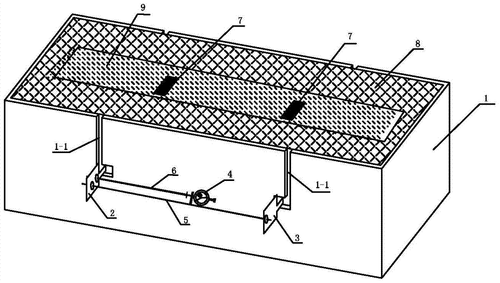
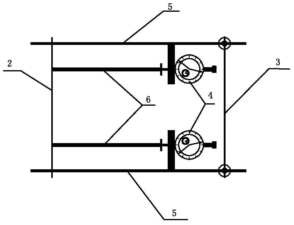
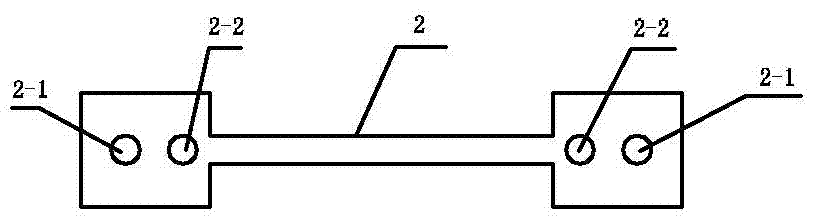
[0012] Specific implementation mode one: combine Figure 1 to Figure 4 Describe this embodiment, the embedded cement-based material composite shrinkage measuring instrument described in this embodiment includes a metal mold 1, a positioning plate 2, a placement plate 3, a measuring instrument 4, an instrument column 5, an instrument top column 6, and an inner wall isolation Layer 8 and two supporting test pieces 7, the metal mold 1 is a box with an upper opening consisting of a front side vertical plate, a rear side vertical plate, a left and right side vertical plate and a bottom plate, and an inner wall isolation layer 8 is placed in the inner cavity of the metal mold 1 On the surface of the body, two transparent L-shaped slots 1-1 are correspondingly opened on the front side vertical board and the rear side vertical board, and the two L-shaped slots 1-1 are respectively opened on the front side vertical board and the rear side vertical board. The center line of the vertical...

specific Embodiment approach 2

[0017] Specific implementation mode two: combination figure 1 Describe this embodiment. This embodiment is a further limitation of the embedded cement-based material composite shrinkage measuring instrument described in Embodiment 1. The measuring instrument 4, the instrument column 5 and the instrument top column 6 are respectively arranged in front of the metal mold 1 at the same time. Outside of side risers, outside of rear side risers.

[0018] The invention further improves the accuracy of the test by adopting simultaneous measurement on both sides.

specific Embodiment approach 3

[0019] Specific implementation mode three: combination figure 1 This embodiment is described. This embodiment is a further limitation of the built-in cement-based material composite shrinkage measuring instrument described in Embodiment 1. The metal mold 1 is made of stainless steel.

[0020] The metal mold 1 is made of stainless steel, fully considering that the metal mold 1 is small in shape, corrosion-resistant, and reusable, thereby reducing the cost of repurchasing the mold.


PUM


Abstract

The built-in cement-based material composite shrinkage measuring instrument relates to a cement-based material composite shrinkage measuring device. The invention solves the error caused by removing the formwork when the test piece is placed horizontally in the process of measuring the composite shrinkage of the existing cement-based material in the laboratory. And vertical placement measurement also needs to remove the formwork and generally use the bottom of the test mold as the measurement reference point to introduce large deviations in measurement data. The present invention includes metal molds, positioning plates, placement plates, measuring instruments, instrument columns, and instrumentation. There are two transparent L-shaped slots on the metal mold, the top column, the inner wall isolation layer and two matching test pieces. The positioning plate and the placement plate are respectively placed at the bottom of the two L-shaped slots. The instrument column It is fixedly connected with the placement plate and contacted with the positioning plate, the measuring instrument is fixedly connected on the instrument column, and two supporting test pieces are respectively placed on the upper surface of the piece to be tested. The invention is applicable to a composite shrinkage measuring device for cement-based materials.

Description

technical field [0001] The invention relates to a measuring device for composite shrinkage of cement-based materials. Background technique [0002] In the actual application process, cement-based materials often undergo volume changes such as chemical shrinkage and plastic shrinkage before complete hardening due to self-hydration and evaporation of water. The volume is increasing, the compactness of the whole system is increasing, and the material is gradually hardening. When the cement-based material has initially set and hardened and has a certain structural strength, the hydration process is still continuing. At this time, the relatively dense solid-phase substance will prevent the macroscopic volume reduction of the system, and the volume reduction caused by the hydration of the material will be in Pores are retained and formed inside the system. After that, the hydration still continues. When the remaining cement-based material continues to hydrate and consumes intern...

Claims


Application Information

Patent Timeline
Patent Type & Authority Patents(China)
IPC IPC(8): G01N33/38
Inventor 葛勇于业宁
Owner HARBIN INST OF TECH
Why Eureka
Try Eureka