Adaptive wave beam formation method

An adaptive beam and beam technology, applied to radio wave measurement systems, instruments, etc., can solve the problems of point scattering target identification defects, low utilization rate of array element information, etc., to improve inconsistency, improve quality, and improve identification Effect

Active Publication Date: 2015-11-11
INST OF ACOUSTICS CHINESE ACAD OF SCI
View PDF3 Cites 5 Cited by
  • Summary
  • Abstract
  • Description
  • Claims
  • Application Information

AI Technical Summary

Problems solved by technology

[0005] Therefore, the existing adaptive beamforming method under the spatial smoothing method has a low utilization rate of the array element information at both ends of the transducer array, resulting in defects in resolution, especially in the identification of point scattering targets.

Method used


Image

  • Adaptive wave beam formation method
  • Adaptive wave beam formation method
  • Adaptive wave beam formation method

Examples


Embodiment Construction

[0037] The technical solutions of the present invention will be described in further detail below with reference to the accompanying drawings and embodiments.

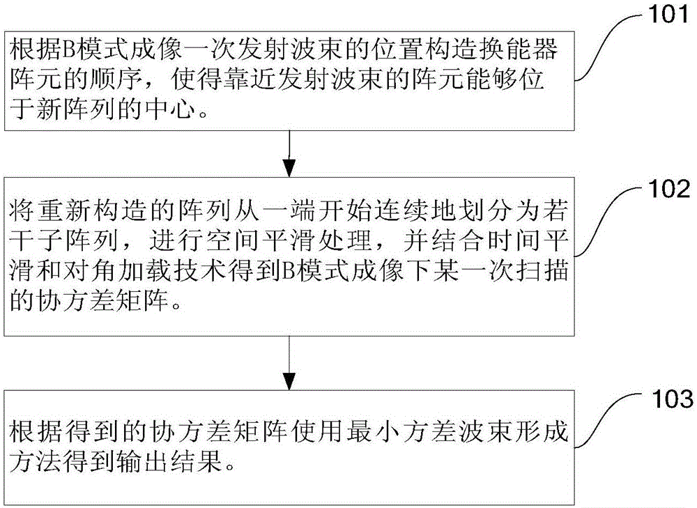
[0038] figure 1 It is a schematic flowchart of an adaptive beamforming method provided by an embodiment of the present invention. Such as figure 1 As shown, the embodiment of the present invention is applied to ultrasound imaging in B mode. The ultrasonic transducer array with M array elements at equal intervals works in the B-mode imaging linear scanning mode, and performs beamforming processing on the received echo data, and each scan line corresponds to the received signal of M array elements , and the sampling data length of each array element is N, these echo data in the time domain have been processed by dynamic focusing, that is, the echo data are "aligned" at each sampling depth, and the obtained x d As the default processing object in the process described below. The beamforming processing method in the em...


PUM


Abstract

The invention relates to an adaptive wave beam formation method. In one embodiment, the method comprises the following steps of reconstructing a sequence of transducer array elements according to a spatial position of an emission wave beam, putting the array element which is close to the wave beam at a center of a new array and putting the array elements which are far away from the wave beam at two ends of the new array; according to the array element sequence which is rearranged, calculating a covariance matrix used for minimum variance wave beam forming; according to the covariance matrix obtained through estimation, calculating an output result of adaptive wave beam formation. In the embodiment of the invention, through reconstructing the sequence of the transducer array elements, echo information of two ends of the array are fully used; inconsistency of resolutions of an image edge area and a center area is improved and quality of ultrasonic imaging is increased.

Description

technical field [0001] The invention relates to a beam forming method in ultrasonic imaging, in particular to an adaptive beam forming method based on an improved spatial smoothing method. Background technique [0002] Traditional medical ultrasonic diagnosis and ultrasonic non-destructive testing systems generally use the beamforming method of time-delay and stacking, and the quality of ultrasonic imaging is poor. [0003] Although the minimum variance adaptive beamforming method can improve the quality of ultrasound imaging, the estimation of the covariance matrix, one of the core problems of the minimum variance beamforming method, requires spatial smoothing because of the strong coherence of the ultrasonic echo signal. deal with. The traditional space smoothing process is to divide the entire array into several sub-arrays, each sub-array contains the same number of array elements, and slide from one end of the array to the other end to construct a set of sub-arrays, and...

Claims


Application Information

Patent Timeline
Patent Type & Authority Applications(China)
IPC IPC(8): G01S7/539
CPCG01S7/539
Inventor 夏新源理华孟晓辉李平
Owner INST OF ACOUSTICS CHINESE ACAD OF SCI
Why Eureka
Try Eureka