Working condition simulation method for device coated with thermal barrier coating

A thermal barrier coating, working condition simulation technology, applied in instruments, special data processing applications, electrical digital data processing and other directions, can solve the complex service environment of thermal barrier coating turbine blades, the coating is prone to cracks, Layer peeling and other problems, to achieve good economic benefits, ensure accuracy, and accurate simulation results

Active Publication Date: 2015-11-11
XIANGTAN UNIV
View PDF4 Cites 24 Cited by
  • Summary
  • Abstract
  • Description
  • Claims
  • Application Information

AI Technical Summary

Problems solved by technology

[0003] However, in the process of practical application, due to the influence of material parameter mismatch and thermal residual stress, high temperature sintering effect of ceramic materials, high temperature creep, high temperature fatigue, high temperature interface oxidation, etc., crack initiation and propagation are prone to occur in the coating , resulting in the peeling off of the thermal barrier coating
Once the coating is peeled off, the base metal parts will be exposed to high temperature environment, and the consequences are very serious
[0004] Therefore, it is very important to study the damage mechanism of thermal barrier coatings in high temperature service environment. However, due to the extremely complex service environment of thermal barrier coating turbine blades, it requires a huge

Method used


Image

  • Working condition simulation method for device coated with thermal barrier coating
  • Working condition simulation method for device coated with thermal barrier coating
  • Working condition simulation method for device coated with thermal barrier coating

Examples


Embodiment Construction

[0043] In order to make the object, technical solution and advantages of the present invention clearer, the present invention will be further described in detail below in combination with specific embodiments and with reference to the accompanying drawings. It should be understood that these descriptions are exemplary only, and are not intended to limit the scope of the present invention. Also, in the following description, descriptions of well-known structures and techniques are omitted to avoid unnecessarily obscuring the concept of the present invention.

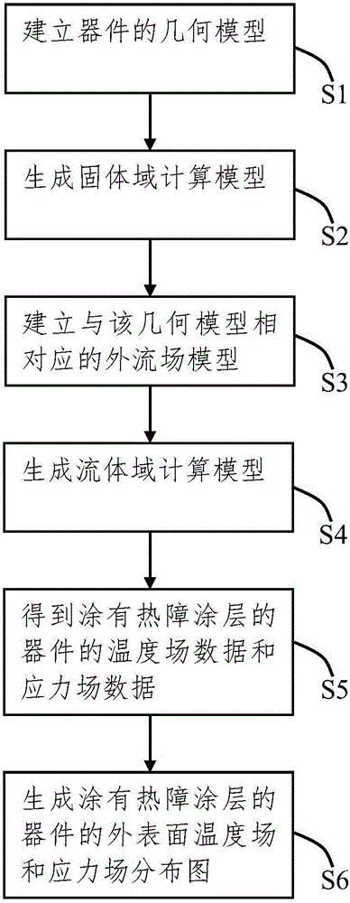
[0044] Such as figure 1 As shown, the working condition simulation method of the device coated with thermal barrier coating of the present invention comprises the following steps:

[0045] S1. In the finite element modeling software, establish the geometric model of the device containing the coating interface and coated with the thermal barrier coating.

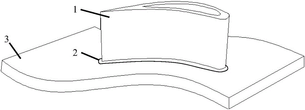
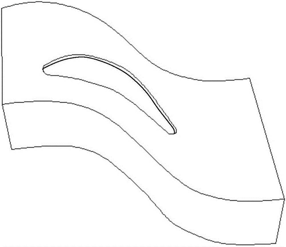
[0046] Such as figure 2 As shown, the device is a turbine blade...


PUM


Abstract

A working condition simulation method for a device coated with a thermal barrier coating. The working condition simulation method comprises the following steps of: S1, establishing a geometrical model that contains a coating interface and is coated with the thermal barrier coating; S2, establishing a solid region calculation model corresponding to the geometrical model; S3, establishing an external flow field model corresponding to the geometrical model in S1; S4, carrying out fluid pre-analysis processing on the external flow field model to generate a fluid region calculation model; S5, obtaining temperature field data and stress field data of the device coated with the thermal barrier coating; and S6, generating an external surface temperature field and a stress field distribution diagram of the device coated with the thermal barrier coating. With the adoption of the simulation method provided by the invention, the movement of fluid of an external fluid field can be accurately simulated, so that the accuracy of the temperature field is guaranteed and the change of structural thermal stress also can be accurately simulated while sufficiently considering the condition of geometrical complexity of the device; and furthermore, the cost of researching a damage mechanism of the thermal barrier coating under a high-temperature service environment is greatly reduced; and economic benefits are good.

Description

technical field [0001] The invention relates to the technical field of heat-insulating protective coating systems in high-performance aero-engines, in particular to a method for simulating working conditions of devices coated with thermal barrier coatings. Background technique [0002] Thermal barrier coatings (TBCs for short) are a layer of ceramic coatings that are deposited on the surface of high temperature resistant metals or superalloys. The thermal barrier coating acts as a heat insulator for the base material, which can reduce the temperature of the base, so that the devices made of it (such as engine turbine blades) can operate at high temperatures, with high melting point, low thermal conductivity, corrosion resistance, Features of thermal shock resistance. During high-temperature service, thermal barrier coatings can protect high-temperature substrates, increase the temperature and thermal efficiency of heat engines, and thus are widely used in the fields of avia...

Claims


Application Information

Patent Timeline
Patent Type & Authority Applications(China)
IPC IPC(8): G06F17/50
Inventor 杨丽朱旺汤文章周益春
Owner XIANGTAN UNIV
Why Eureka
Try Eureka