Sheet metal part sagging compensation design method

A technology of sheet metal parts and design method, applied in the field of sheet metal parts processing, can solve the problems of unfavorable mass production, poor quality of manual blanking, inaccurate blanking size, etc., so as to reduce the risk of small manual blanking and save money. cost, improve work efficiency

Active Publication Date: 2015-11-11
SHENYANG AIRCRAFT CORP
View PDF3 Cites 2 Cited by
  • Summary
  • Abstract
  • Description
  • Claims
  • Application Information

AI Technical Summary

Problems solved by technology

However, it is not accurate enough for workers to increase the blanking size based on personal experience, and it cannot completely avoid the occurrence of small parts. The quality of manual blanking is poor and the efficiency is low, which is not conducive to mass production.

Method used


Image

  • Sheet metal part sagging compensation design method
  • Sheet metal part sagging compensation design method
  • Sheet metal part sagging compensation design method

Examples


Embodiment

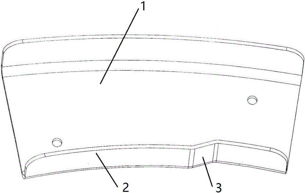
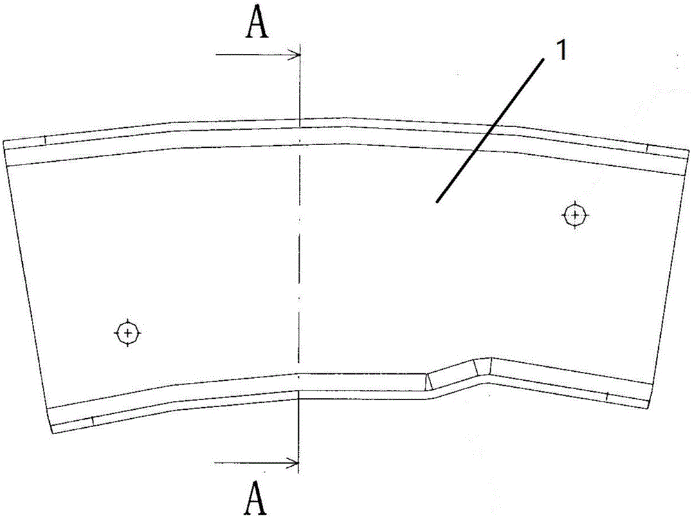
[0029] Such as Figure 1-3 The flange 2 of a sheet metal part 1 shown has a depression 3, such as Figure 4 Shown is the unwrapped dataset for this Sheet Metal Part 1. The data set has the shape boundary line 4 of the sheet metal part 1 and the tangent line 5 of the inner corner of the flange. The temporary point of deformation of gold part 1.

[0030] A design method for sag compensation of sheet metal parts, comprising the following steps,

[0031] 1) Expand the data set for the sheet metal part 1 with sag, and set the shape boundary line 4 with 3 sags in the data set to L 3 , sheet metal part 1 with L 3 An adjacent outline boundary line 4 is set to L 1 ;

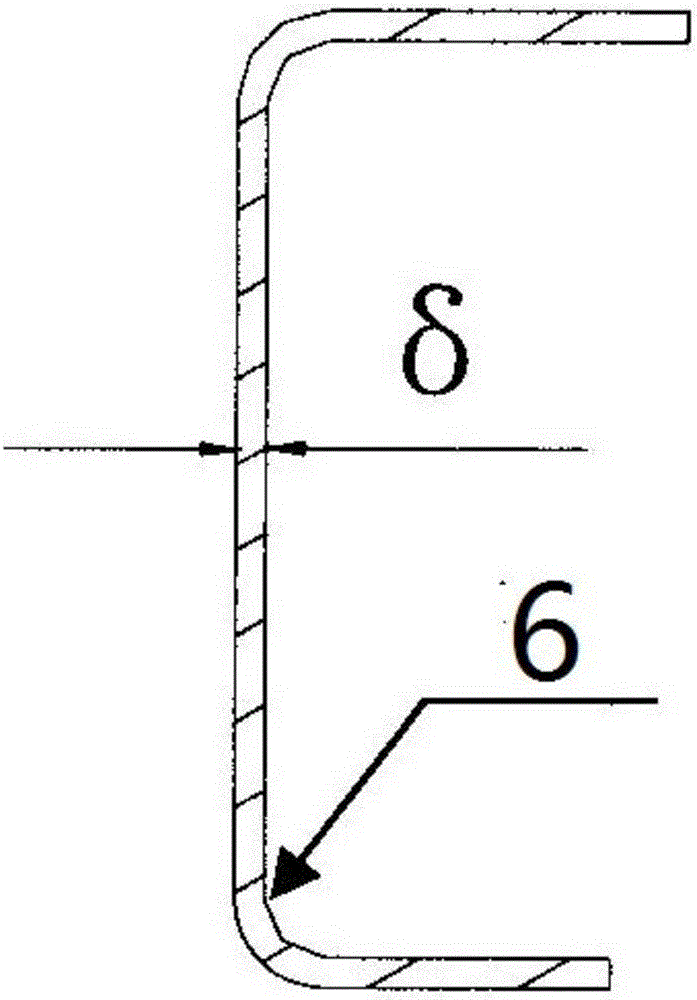
[0032] 2) In the data set, select the critical point of the deformation of the sagging end of the flange 2 in the sheet metal part 1 as the starting point C of the sag expansion compensation 7; specifically, in the data set, use the tangent point 6 of the inner corner of the bending edge of the sheet metal part as t...


PUM


Abstract

The invention discloses a sheet metal part sagging compensation design method comprising steps of first, expanding a data set of a sagging sheet material part, second, selecting a critical point of sagging end head deformation of a bend side of the sheet material part in the data set as a sagging compensation start point (C), third, designing a maximum value point (B) of expansion value of the sheet material part in the data set to acquire a line section (BC) and connecting points (B, C) to form a line section (BC), fourth, acquiring a tangent line to a sagging arc of the sheet material part via the B point in the data set, and fifth, chamfering between the line section (BC) and a line section (BD) to form a sealed area, then achieving sagging expansion compensation. In the first step, an outline border line of the sagging part in the data set is designated to be L3; the outline border line of one side of the sagging part of the sheet material part is designated to be L1; L1 and L3 are adjacent to each other; a tangency point between the tangent line and the sagging arc is D; and points (D, B) are connected to form a line section (BD). Sheet material part blanking accuracy and work efficiency can be improved; and manufacturing cost can be reduced.

Description

technical field [0001] The invention relates to the field of sheet metal parts processing, in particular to a design method for sag compensation of sheet metal parts. Background technique [0002] In the process of aircraft manufacturing, sheet metal parts are the most common type of parts. Due to the high precision of aircraft manufacturing and assembly, it requires high processing accuracy of sheet metal parts. However, among the sheet metal parts, there are many sheet metal parts with sags. This kind of parts has a special structure, and the expanded size calculated according to the calculation formula often does not conform to the actual production. The parts will shrink strongly at the sag during the forming process. The local size of sheet metal parts will be too small near the sunken trimming, which will lead to out-of-tolerance and scrapping of parts. For sheet metal parts with sag produced in batches, such problems need to be solved urgently. In order to solve the ...

Claims


Application Information

Patent Timeline
Patent Type & Authority Applications(China)
IPC IPC(8): G06F17/50
Inventor 张云鹏时贵雨安冬梅
Owner SHENYANG AIRCRAFT CORP
Why Eureka
Try Eureka