Passive cooling system for retention of melts in serious accident state of reactor

A passive cooling and severe accident technology, applied in reactors, cooling devices, nuclear power generation, etc., can solve problems such as poor applicability

Active Publication Date: 2015-11-11
NUCLEAR POWER INSTITUTE OF CHINA
View PDF9 Cites 16 Cited by
  • Summary
  • Abstract
  • Description
  • Claims
  • Application Information

AI Technical Summary

Problems solved by technology

Therefore, for medium and high power modular reactors with sma

Method used


Image

  • Passive cooling system for retention of melts in serious accident state of reactor
  • Passive cooling system for retention of melts in serious accident state of reactor
  • Passive cooling system for retention of melts in serious accident state of reactor

Examples


Embodiment 1

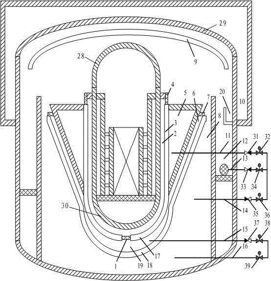
[0027] Such as figure 1 The shown passive cooling system for molten matter retention under severe reactor accident state includes pressure vessel annular cavity water inlet 1, pressure vessel annular cavity 2, pressure vessel annular cavity wall 3, pressure vessel annular cavity steam exhaust hole 4, Annular cavity pool 5, pool annular cavity 6, pool annular cavity exhaust hole 7, crucible cooling pool 8, steel containment upper pool 10, annular pool drainage pipeline 11, recirculation pit 12, recirculation pipeline 13, crucible cooling Pool water supply pipeline 14, crucible chamber water supply pipeline 15, crucible cooling pool drainage pipeline 16, crucible 18, crucible chamber 19.

[0028] Among them, the pressure vessel annular cavity 2 is formed between the pressure vessel wall surface and the annular cavity wall surface 3, and the pressure vessel annular cavity steam exhaust hole 4 is arranged on the top of the pressure vessel annular cavity 2; the annular cavity water...

Embodiment 2

[0041] On the basis of Example 1, it is also possible to set a condensed water diversion device for more efficient diversion of water vapor on the containment, and a more efficient collection of condensed water collection devices

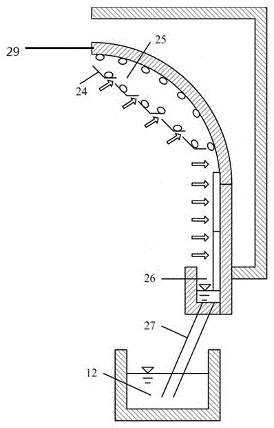
[0042] like image 3 As shown, the condensed water diversion device 9 is installed on the arc-shaped inner surface of the steel containment vessel 29 and is composed of a plurality of guide plates 24 with gaps between the guide plates 24 to form a condensation annular gap 15 with the steel containment vessel 29 .

[0043] The water collection device 20 is installed in the cylinder of the steel containment vessel 29 and consists of a sump 26 surrounding the inner surface of the containment vessel and a diversion channel 27 .

[0044] The working process of the condensate diversion device and the water collection device is as follows: the water vapor in the steel containment spherical head enters the condensation annulus 25 through the gap between the...

Embodiment 3

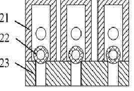
[0046] On the basis of the above embodiments, the structure of the water inlet hole 1 and the annular cavity exhaust hole 4 of the pressure vessel can be further optimized, so that the water inlet hole 1 and the exhaust hole 4 are only opened when the fluid passes through, and closed at other times.

[0047] like figure 2 As shown, the water inlet hole 1 of the annular chamber of the pressure vessel is composed of a punching plate 23 , a guide pipe 21 with holes and an equal amount of hollow stainless steel floating balls 22 . Under normal circumstances, the hollow stainless steel floating ball 22 is still in the guide tube of the punching plate, and the water inlet hole is closed. The guide pipe 21 flows to the annular cavity 2 of the pressure vessel, submerging and cooling the wall surface of the pressure vessel.

[0048] The vent hole 4 of the annular cavity of the pressure vessel is covered by a light floating plate. When the fluid and water vapor in the annular cavity 2...


PUM


Abstract

The invention provides a passive cooling system for the retention of melts in the serious accident state of a reactor. The passive cooling system comprises a pressure vessel ring cavity between a pressure vessel wall surface and a ring cavity wall surface, wherein steam discharging holes are formed in the top of the ring cavity, and a water inlet is formed in the bottom of the ring cavity; a ring cavity water tank surrounds the ring cavity wall surface, a crucible is arranged at the part, which is not encircled by the ring cavity water tank, of the ring cavity wall surface of the water tank to encircle the part so as to form a crucible cavity, the crucible extends upwards to form a water tank ring cavity, and the top of the water tank ring cavity is provided with gas discharging holes so as to be communicated with the crucible chamber; a crucible cooling water tank is arranged at the periphery of the crucible, an opening is formed in the top of the crucible cooling water tank, a steel safety shell is arranged at the periphery of the crucible cooling water tank, and an upper water tank surrounds the upper half part of the steel safety shell; the ring cavity water tank is communicated with the crucible cooling water tank through a pipeline; a re-circulation pit is arranged inside the steel safety shell, and is communicated with the crucible cooling water tank through a pipeline; the crucible cavity is communicated with the crucible cooling water tank through a pipeline. According to the technical scheme, three stages of cooling and retention of the melts of a reactor core can be realized according to different decay heat energies in accident sequences.

Description

technical field [0001] The invention relates to a passive cooling system for the inside and outside of the reactor core molten matter staying in the reactor severe accident state, and is especially suitable for medium and high-power modular reactors with small steel containment shells. Background technique [0002] At present, in the design of advanced third-generation reactors at home and abroad, there are two main strategies to realize the cooling and retention of core melt in order to alleviate severe accidents: (1) cooling and retention of melt inside the reactor; (2) cooling of melt outside the reactor and stranded. [0003] At present, in the design of advanced third-generation reactors at home and abroad, there are two main strategies to achieve core melt cooling and retention in order to alleviate severe accidents: 1. Melt internal cooling and retention strategy (IVR); 2. Melt stack External cooling and retention. The application of the first strategy is represente...

Claims


Application Information

Patent Timeline
IPC IPC(8): G21C15/18
CPCY02E30/30
Inventor 向清安邓坚孔翔程邹志强陈宝文朱大欢武铃珺
Owner NUCLEAR POWER INSTITUTE OF CHINA
Why Eureka
Try Eureka