
Inner guide duct transformer

A transformer and air duct type technology, applied in the field of inner duct type transformers, can solve the problems of affecting voltage conversion efficiency, unfavorable cooling of transformer oil, and low heat dissipation efficiency, so as to maintain heat dissipation efficiency, stabilize heat dissipation efficiency, and improve heat dissipation efficiency Effect

Active Publication Date: 2015-11-11
CHONGQING MINSHENG TRANSFORMER
View PDF8 Cites 10 Cited by
  • Summary
  • Abstract
  • Description
  • Claims
  • Application Information

AI Technical Summary

Problems solved by technology

Heat is generated during the working process of the transformer. Too high temperature will affect the efficiency of voltage conversion and increase the loss. Therefore, the design of the transformer attaches great importance to the heat dissipation performance. Existing transformers generally use heat dissipation pipes. The heat dissipation pipes are made of The exposed hollow tube made of a good thermal conductor, the upper and lower ends are respectively connected with the upper and lower parts of the inner space of the transformer oil tank to form a circulation loop. The heat dissipation tubes of this structure dissipate heat into the air by direct contact with the air. The fluidity of the air is crucial to its radiation efficiency. When there is no wind, this structure cannot form a large convection, so the heat dissipation efficiency is low, especially in the case of direct sunlight, the facing surface of the heat dissipation pipe absorbs solar energy and dissipates the heat. Transferred to the backlight surface, the body temperature of the heat dissipation pipe under the light is much higher than the outside air temperature, which is not conducive to the cooling of the transformer oil, and these still need to be solved technically

Method used


Image

  • Inner guide duct transformer
  • Inner guide duct transformer

Examples


Embodiment Construction

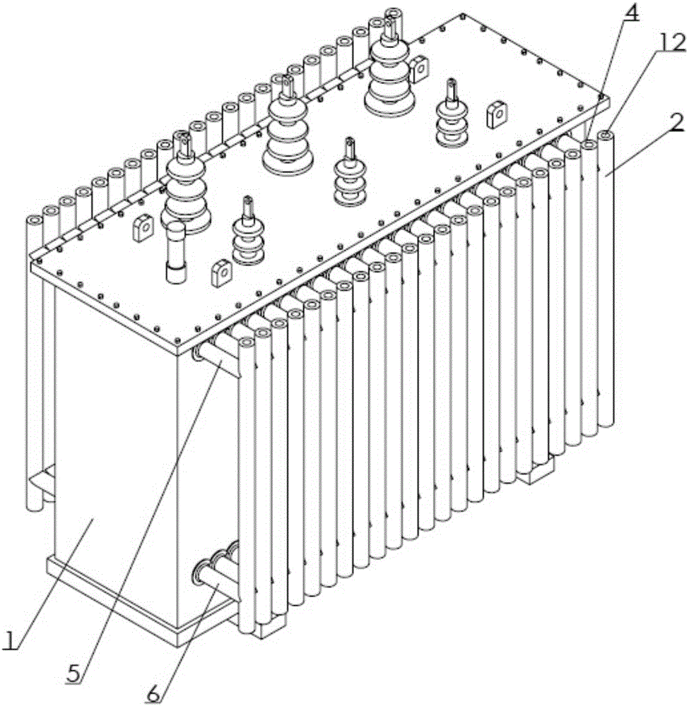
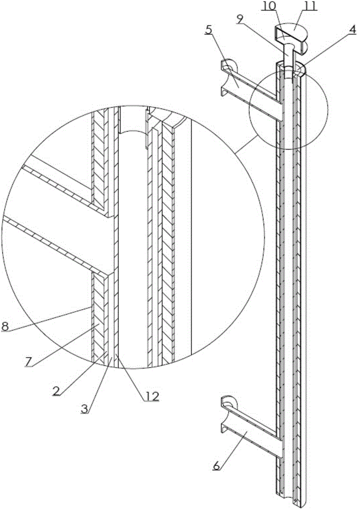
[0013] Embodiments of the present invention are as figure 1 As shown, the inner air guide tube transformer is provided with an oil tank 12 with an iron core inside and filled with transformer oil, and a number of vertical heat dissipation pipes arranged in an array on the side of the oil tank. The heat dissipation pipes are provided with an inner pipe 1, The outer tube 2 is sheathed on the outside of the inner tube. Both the inner and outer tubes are made of thermally good conductor materials. There is a gap between the inner tube wall and the outer tube wall to form an annular flow channel 3. The ends of the inner and outer tubes of the flow channel The head is provided with a plug 4, the upper end of the outer pipe is connected with an upper communication pipe 5 communicating with the annular flow passage, the lower end of the outer pipe is connected with a lower communication pipe 6 communicating with the annular flow passage, and the upper communication pipe communicates wi...


PUM


Abstract

The invention discloses an inner guide duct transformer, which comprises an oil tank and radiating pipes, wherein an iron core is arranged in the oil tank; the oil tank is fully filled with transformer oil; an inner pipe is arranged in each radiating pipe; an outer pipe sleeves the outside of each the inner pipe; a gap is formed between the wall of each inner pipe and the wall of each outer pipe to form an annular channel; the channel is provided with plugs at the terminals of each inner pipe and each outer pipe; the upper end of each outer pipe is connected with an upper communicating pipe which is communicated with each annular channel; the lower end of each outer pipe is connected with a lower communicating pipe which is communicated with each annular channel; each upper communicating pipe is communicated with the upper part of an internal space of the oil tank; and each lower communicating pipe is communicated with the lower part of the internal space of the oil tank. According to the inner guide duct transformer, air in the inner pipes is heated to ascend and flows out from upper openings, so as to form relatively strong convection; the radiating area is large; the effects on the inner pipes caused by illumination temperature rise are small; the radiating efficiency is improved; and the radiating efficiency is stable.

Description

technical field [0001] The invention relates to an equipment transformer in the electric power industry, in particular to an inner air guide tube type transformer. Background technique [0002] my country has a vast territory and a dense power transmission network. Transformers are needed at the end of the network to convert voltage. Heat is generated during the working process of the transformer. Too high temperature will affect the efficiency of voltage conversion and increase the loss. Therefore, the design of the transformer attaches great importance to the heat dissipation performance. Existing transformers generally use heat dissipation pipes. The heat dissipation pipes are made of The exposed hollow tube made of a good thermal conductor, the upper and lower ends are respectively connected with the upper and lower parts of the inner space of the transformer oil tank to form a circulation loop. The heat dissipation tubes of this structure dissipate heat into the air by ...

Claims


Application Information

Patent Timeline
IPC IPC(8): H01F27/08F28D7/10
Inventor 李金仁陈明德
Owner CHONGQING MINSHENG TRANSFORMER
Features
  • Generate Ideas
  • Intellectual Property
  • Life Sciences
  • Materials
  • Tech Scout
  • Unparalleled Data Quality
  • Higher Quality Content
  • 60% Fewer Hallucinations
Learn More