Packaging flexible substrate and packaging body

A flexible substrate and substrate technology, which is used in identification devices, electric solid devices, semiconductor devices, etc., can solve the problems of separation of wires and substrates affecting packaging performance and reliability, and achieves advantages such as promotion and application, simple structure, and manufacturing process. mature effect

Inactive Publication Date: 2015-11-11
BOE TECH GRP CO LTD
View PDF3 Cites 18 Cited by
  • Summary
  • Abstract
  • Description
  • Claims
  • Application Information

AI Technical Summary

Problems solved by technology

[0004] The technical problem to be solved by the present invention is that the breakage of the wire or the separation of the wire from the substrate in the existing flexible substrate packaging greatly affects the packaging performance and reliability.

Method used


Image

  • Packaging flexible substrate and packaging body
  • Packaging flexible substrate and packaging body
  • Packaging flexible substrate and packaging body

Examples


Embodiment 1

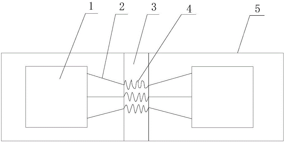
[0032] Such as figure 1 As shown, this embodiment provides a flexible substrate for packaging, wherein a bending area 3 is provided in the middle of the flexible substrate 5, and chips 1 are provided on both sides of the bending area 3 and at both ends of the flexible substrate 5. . The wires 2 passing through the bending area 3 are connected between the two chips 1, and the wires 2 can include all the wires in the bending area 3 of the flexible substrate (that is, the wires on the inner surface of the bend, the wires on the outer surface of the bend, and the bends on the flexible substrate. In addition, a section of the wire 2 corresponding to the bending area 3 is provided with an anti-stress structure 4, that is to say, the part of the wire 2 located in the bending area 3 is provided with an anti-stress structure 4. The anti-stress structure 4 is used to release the tensile and compressive stress when the bending area 3 is bent, so as to improve the reliability of the wire...

Embodiment 2

[0037] The technical content of the second embodiment that is the same as that of the first embodiment will not be described repeatedly. The content disclosed in the first embodiment also belongs to the content disclosed in the second embodiment. The second embodiment is obtained by further modification on the basis of the first embodiment.

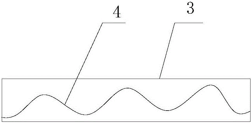
[0038] Such as figure 2 As shown, the stress-resisting structure 4 is a sub-conductor that can undergo tensile and compressive deformation on the conductor 2, and the sub-conductor is distributed in a sinusoidal curve in the bending area 3, that is, the sub-conductor is a section with crests and troughs. of wavy lines. Moreover, the sub-wires are arranged transversely through the bending area 3 . When the bending area 3 is bent, the sub-wire will release stress along the direction of tension and compression during the bending process, so as to avoid the breakage of the wire or the separation of the wire from the substrate, which greatly...

Embodiment 3

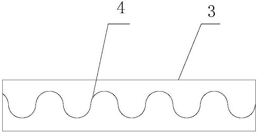
[0040] Such as image 3 As shown, in order to increase the effect of releasing the stress, the third embodiment is improved on the basis of the second embodiment, and the shape of the sub-conductors is changed to a continuous "S" shape distribution, that is, the sub-conductors are distributed in the bending area 3 It is distributed in a continuous "S" shape. This continuous "S" shape can be understood as a plurality of English letters "S" connected in sequence and transversely running through the bending area 3 . Wherein, the letter "S" is used as an example to explain and illustrate for the convenience of understanding, and other shapes similar to the letter "S" also belong to the protection scope of the third embodiment. Moreover, since the bending length of the sub-conductor in the third embodiment is greater than that of the sub-conductor in the second embodiment within the range of unit length, it can release greater stress when it is bent, and the stress is released dur...


PUM


Abstract

The invention relates to the technical field of display, and specifically relates to a packaging flexible substrate and a packaging body. The middle of the packaging flexible substrate is provided with a bending area. The two ends of the flexible substrate are respectively provided with a chip. Wires passing through the bending area are connected between the chips. Each wire is provided with a stress-resistant structure in a section corresponding to the bending area, and the stress-resistant structure is used to release anti-tensile and anti-compression stress when the bending area bends. Therefore, the reliability of the wires in the process of flexible substrate 3D stacked packaging bending is improved, and the problems greatly affecting the packaging performance and reliability, such as wire breakage or wire and substrate separation during use of the existing flexible substrate, are solved effectively. The packaging flexible substrate is simple in structure, convenient to operate, and suitable for popularization and application.

Description

technical field [0001] The present invention relates to the field of display technology, in particular to a flexible substrate for packaging and a packaging body, in particular to a flexible substrate and a packaging body for 3D folding packaging. Background technique [0002] At present, in the existing integrated packaging of chips and devices using flexible substrates, more and more dense wiring will be generated on the flexible substrates as the number of devices increases and the degree of integration increases. At the same time, the radius of curvature of the bending area in the 3D folding package utilizing the flexibility of the flexible substrate will also become smaller and smaller. During this process, the dense wiring in the bending area will cause the breakage of the wire or the separation of the wire from the substrate when the bending radius becomes smaller or the packaged product is used for repeated bending operations at medium and high frequencies, which wil...

Claims


Application Information

Patent Timeline
Patent Type & Authority Applications(China)
IPC IPC(8): H01L27/12
CPCH01L27/1218H01L27/12G09F9/301H05K1/028H05K2201/09263H05K2201/10287H01L23/5386H01L23/5387H01L23/562H01L25/0655
Inventor 张博李文波
Owner BOE TECH GRP CO LTD
Why Eureka
Try Eureka