Equipment for switching load speed between power frequency rotating speed and permanent magnet speed adjustment

A technology of permanent magnet speed regulation and load speed, applied in the power field, can solve the problems of small footprint, small maintenance, and only shutdown of permanent magnet governors, so as to avoid economic benefits and social impacts, save time and Artificial, to avoid the effect of demolition construction

Active Publication Date: 2015-11-11
GUODIAN LONGYUAN ENERGY SAVING TECH
View PDF3 Cites 0 Cited by
  • Summary
  • Abstract
  • Description
  • Claims
  • Application Information

AI Technical Summary

Problems solved by technology

The permanent magnet governor occupies a small area, does not need to be additionally installed to install the house and the air conditioner to cool down, the maintenance amount is small, and the equipment life is long, but there is a weakness that the permanent magnet governor cannot be widely used at present, that is, the permanent magnet The governor is directly installed between the motor and the load. Once the permanent magnet governor fails, it can only be shut down, and then the permanent magnet governor can be repaired. If the fault cannot be eliminated quickly, the permanent magnet governor can only be adjusted. Remove the inverter and return it to the factory, move the motor forward, and reconnect and fix it with the load
For large-scale rotating equipment without backup, the inability to quickly switch to power frequency after a permanent magnet governor fails is a major defect that energy-consuming units cannot accept, and it is also the main power plant that has not adopted permanent magnet speed regulation in fans. s reason

Method used


Image

  • Equipment for switching load speed between power frequency rotating speed and permanent magnet speed adjustment
  • Equipment for switching load speed between power frequency rotating speed and permanent magnet speed adjustment
  • Equipment for switching load speed between power frequency rotating speed and permanent magnet speed adjustment

Examples


Embodiment Construction

[0019] In order to make the object, technical solution and advantages of the present invention clearer, the implementation manner of the present invention will be further described in detail below in conjunction with the accompanying drawings.

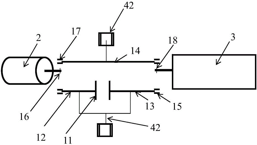
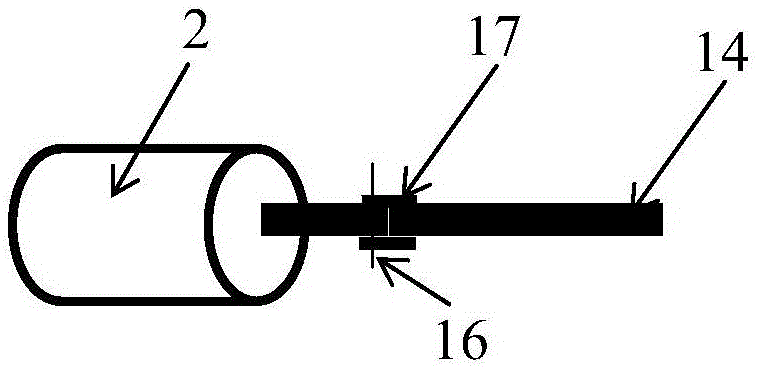
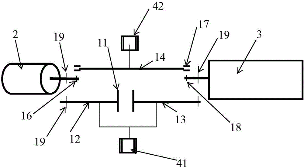
[0020] see Figure 1~3 , The present invention provides a device for switching the load speed between power frequency speed and permanent magnet speed regulation, which includes: a permanent magnet speed regulation unit, a power frequency speed unit and a switching unit. The permanent magnet speed control unit and the power frequency speed unit are both arranged between the motor 2 and the load 3. For the convenience of switching, the permanent magnet speed control unit and the power frequency speed unit are arranged on the output shaft of the motor 2 or the input shaft of the load 3. both sides of the axis. The motor 2 is used to drive the load 3 to run, and the load 3 is a rotating device, such as a fan or a pump.

[0021] Specific...


PUM


Abstract

The invention discloses equipment for switching load speed between power frequency rotating speed and permanent magnet speed adjustment and belongs to the field of power. The equipment comprises a permanent magnet speed adjustment unit, a power frequency rotating speed unit and a switching unit; the switching unit is used for enabling the permanent magnet speed adjustment unit and the power frequency rotating speed unit to switch between the load and an electromotor. Through the above technical solution, the operation such as the dismantling construction of a permanent magnet speeder is avoided while the permanent magnet speeder is in fault, so the time and the labor are greatly saved, and the economic benefit and the social influence brought by the condition that a unit could not operate with load for a long time are further avoided.

Description

technical field [0001] The invention belongs to the field of power, and in particular relates to a device for switching the load speed between power frequency speed and permanent magnet speed regulation. Background technique [0002] Large rotating equipment, such as fans and pumps, on the one hand, have large design margins for safe operation; on the other hand, because fans and pumps and other equipment cannot operate at full load, and some equipment is even at low load for a long time, fans and pumps The flow is controlled by the baffle and the valve respectively, resulting in a large throttling loss. The power of the load is proportional to the cubic ratio of the motor speed. The motor itself consumes a lot of energy when the power frequency speed is low at low load. If the motor speed can be properly reduced when the load is low, there will be a large space for reducing consumption. Therefore, speed control equipment: frequency converter and permanent magnet speed gove...

Claims


Application Information

Patent Timeline
IPC IPC(8): H02K51/00
CPCH02K7/10H02K49/102H02K49/108
Inventor 丁兆勇郭冰赵虎军
Owner GUODIAN LONGYUAN ENERGY SAVING TECH
Why Eureka
Try Eureka