
Load adaptive current peak limited power tube connection method

A technology of current peak and power tube, which is applied in the real-time control of power tube turn-on speed and the field of power tube drive circuit, which can solve the problem of large current peak

Active Publication Date: 2015-11-11
NANJING UNIV OF AERONAUTICS & ASTRONAUTICS
View PDF2 Cites 6 Cited by
  • Summary
  • Abstract
  • Description
  • Claims
  • Application Information

AI Technical Summary

Problems solved by technology

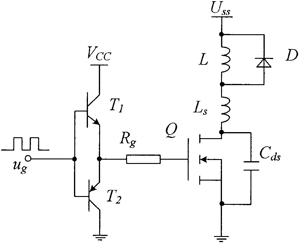
[0003] attached figure 1 It is a traditional voltage source driving method. When the power transistor Q is turned on, due to the reverse recovery current of the freewheeling diode D and the junction capacitance C ds The discharge current, which will generate a current spike on the power switch tube, and the faster the turn-on speed, the larger the current spike

Method used


Image

  • Load adaptive current peak limited power tube connection method
  • Load adaptive current peak limited power tube connection method
  • Load adaptive current peak limited power tube connection method

Examples


Embodiment Construction

[0029] The present invention will be further elaborated below with a specific example, and the technical scheme is attached Figure 9 Shown, but not limited to the technical solution of the present invention.

[0030] attached Figure 9 It is a load-adapted peak current-limited power tube turn-on speed-controlled Boost high-frequency DC converter, which includes four parts: (1) Boost DC converter; (2) average current control circuit; (3) turn-on Speed ​​control circuit; (4) drive circuit.

[0031] The (1) Boost DC converter is a non-isolated high-frequency DC converter, which is composed of an input voltage source U in , inductance L, main power switch tube Q 0 , rectifier diode D 0 , the output filter capacitor C o , load resistance R L , current sense resistor R s and the voltage sense resistor R 1 and R 2 composition.

[0032] The input voltage source U in The positive pole of the inductor is connected to the left end of the inductor L, and the input voltage sour...


PUM


Abstract

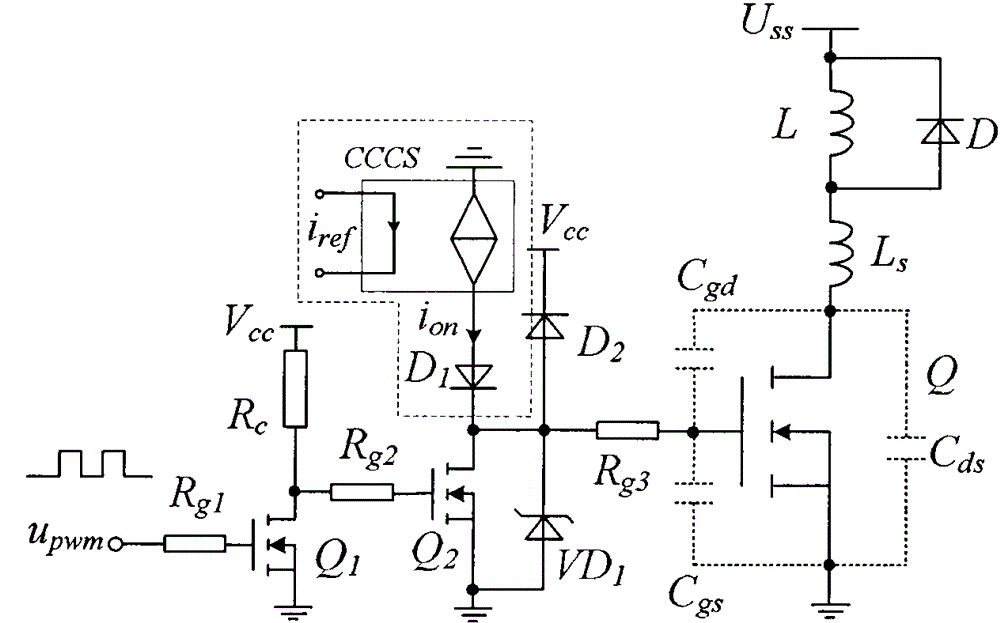
The invention discloses a load adaptive current peak limited power tube connection method. In a power tube driving circuit of a high-frequency direct current converter, a controllable current source is constructed, and the controllable current source is in series connection with the connection loop of the driving circuit. By utilization of the constructed controllable current source, a junction capacity of a power tube Q is charged to disconnect a power tube. The output current of the controllable current source, namely the connection current of the power tube is controlled by the load current value of the converter, and therefore the connection speed of the power tube can be subjected to real time tracking adjustment along with change of the load current. The driving connection current value of the power tube is increased along with decrease of the load to raise a connection speed of the power tube under a condition being less than a rated load, the connection loss of the power tube under a condition being less than the rated load is lowered, and the working efficiency of the converter is raised. During the connection speed real-time adjustment process, the current peak flowing past the power tube is limited to a peak value flowing under a rated load condition and safe and reliable work of the power tube is ensured.

Description

technical field [0001] The invention belongs to the field of power tube drive circuits of high-frequency direct-current converters, in particular to the field of real-time control of the turn-on speed of the power tube. Background technique [0002] In the high-frequency DC converter, the drive circuit is the bridge between the control circuit and the main circuit. The drive circuit of the power tube affects its switching speed, voltage and current peaks, and also affects the EMI of the converter and the working efficiency of the converter. . However, the turn-on speed is inconsistent with the turn-on loss and the turn-on current peak. The faster the turn-on speed of the power tube is, the smaller the turn-on loss and the larger the current peak are; the slower the turn-on speed is, the greater the turn-on loss is, but the turn-on The current peak will be relatively small, therefore, the reasonable design of the driving circuit is particularly important. [0003] attached ...

Claims


Application Information

Patent Timeline
Patent Type & Authority Applications(China)
IPC IPC(8): H02M1/08H02M1/06
Inventor 伍群芳王勤陈仲肖岚徐佳林
Owner NANJING UNIV OF AERONAUTICS & ASTRONAUTICS
Learn More