Conformable balloon devices and methods
A technology of airbags and medical devices, applied in the direction of balloon-shaped catheters, stents, catheters, etc., can solve problems such as airbag bending, blood vessel straightening and damage
- Summary
- Abstract
- Description
- Claims
- Application Information
AI Technical Summary
Problems solved by technology
Method used
Image
Examples
example 2
[0085] Example 2 - Construction of a medical balloon comprising an 8mm nominal diameter according to the present disclosure:
[0086] A tubular precursor was formed as follows: The precursor material from Example 1 with a slit width of 1.25 inches was wound around an 8.5 mm mandrel at approximately 85 degrees relative to the longitudinal axis of the mandrel. Repeat the winding in the opposite direction on the diagonal to complete a total of four times over a length of 100 mm. This tubular precursor was then heat treated in a furnace at 380° C. for 11 minutes and then removed from the furnace. The tubular precursor was removed from the mandrel and stretched axially to reduce its diameter to approximately 1.8 mm. The tubular precursor was then placed on a mandrel having an outer diameter of approximately 1.8mm and cut to 108mm. The tube assembly was then axially compressed to approximately 72% of its original length.
[0087] A compliant polyurethane balloon catheter with a s...
example 3
[0088] Example 3 – Compressive and Tensile Strain Test Method and Results:
[0089]Test Method: First, a 0.9 mm PTFE coated stainless steel mandrel is inserted through the lumen of the balloon catheter to be tested. The balloon is inflated to the nominal inflation pressure. Close the inflation valve. The working length outer surface of the airbag is measured and marked at 10mm intervals around its circumference. The inflation valve is then opened and the balloon is allowed to deflate. Remove the mandrel and use a 0.035" guide wire (AMPLATZSUPER The guide wire, Boston Scientific, Natick, MA, USA) was replaced, ensuring that the flexible section of the guide wire was below the balloon portion of the catheter.
[0090] The balloon to be tested was then inserted into an 8 mm inner diameter x 12 mm outer diameter polyurethane tubing (Part No. 50315K281, McMaster-Carr, Santa Fe Springs, CA, USA). The area where the balloon is positioned within the tube is lubricated with a thi...
example 4
[0094] Example 4 - Method for calculating theoretical compressive and tensile strains:
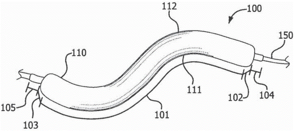
[0095] To gain insight into the strain values observed in Example 3, the theoretical strain values required to maintain the neutral axis can be compared to the observed values. Theoretical compressive and tensile strains can be calculated as follows. Figure 10 is a schematic diagram of the test setup described in Example 3. Tube 1000 is shown in a curved configuration. The neutral axis “NA” is co-located radially with the pipe 1000 . When a balloon co-diametrically aligned with the catheter is inserted into tube 1000, the central axis of the balloon will match this neutral axis. The working length of the airbag will have an arc length aligned along the neutral axis. The angle θ is calculated according to the following formula:
[0096] θ=S / r, where S is the arc length, r is the radius, and θ is the angle in radians.
[0097] Using this approach, if a balloon with a working lengt...
PUM
| Property | Measurement | Unit |
|---|---|---|
| Length | aaaaa | aaaaa |
| Length | aaaaa | aaaaa |
| Diameter | aaaaa | aaaaa |
Abstract
Description
Claims
Application Information
 - R&D
- Intellectual Property
- Life Sciences
- Materials
- Tech Scout
- Unparalleled Data Quality
- Higher Quality Content
- 60% Fewer Hallucinations
Browse by: Latest US Patents, China's latest patents, Technical Efficacy Thesaurus, Application Domain, Technology Topic, Popular Technical Reports.
© 2025 PatSnap. All rights reserved.Legal|Privacy policy|Modern Slavery Act Transparency Statement|Sitemap|About US| Contact US: help@patsnap.com


