Crane

A technology for cranes and actuating cylinders, applied in the field of cranes, can solve problems such as extra stress in stroke length, and achieve long-lasting operation, low center of gravity, and light weight

Active Publication Date: 2015-11-11
PONSSE
View PDF10 Cites 1 Cited by
  • Summary
  • Abstract
  • Description
  • Claims
  • Application Information

AI Technical Summary

Problems solved by technology

In addition, the strokes of the parallel cylinders must be made exactly the same length, otherwise the difference in stroke lengths also creates severe additional stresses in the structure

Method used


Image

  • Crane
  • Crane
  • Crane

Examples


Embodiment Construction

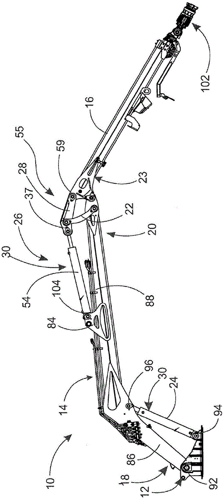
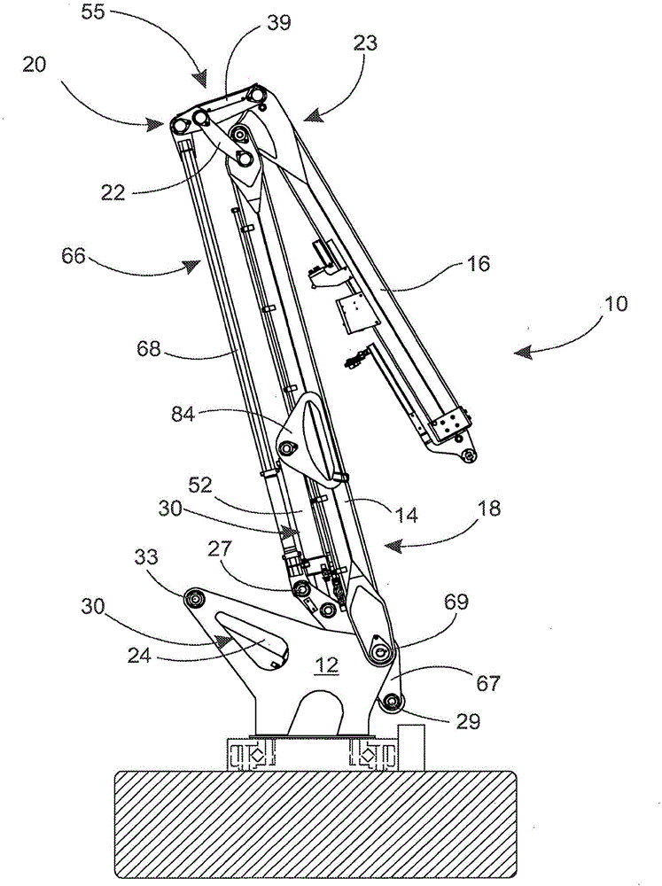
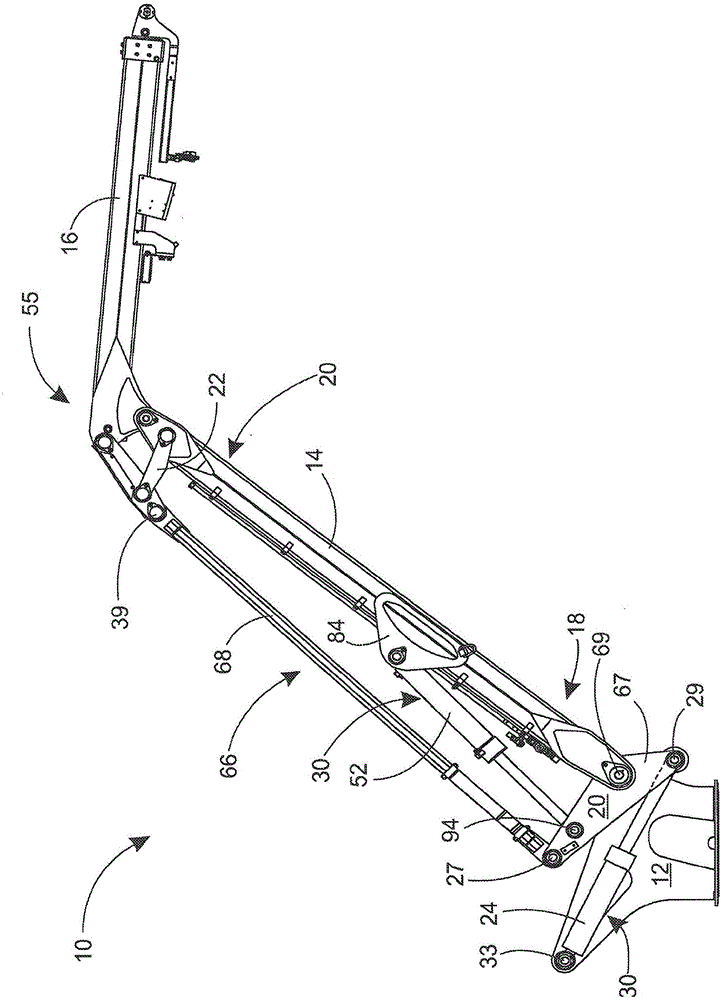
[0098] Figures 1 a and 1 b show a prior art crane 10 . The crane 10 shown in the figures is a motion path crane comprising a base 12 , a main jib 14 pivotally connected to the base 12 , an articulated jib 16 pivotally connected to the main jib 14 . Booms 14 and 16 of crane 10 are operated with the assistance of two actuating cylinders 30 , one of which is lift cylinder 24 and the other is articulation cylinder 52 .

[0099] According to FIGS. 1 a and 1 b , in the prior art crane 10 , the folding movement between the booms 14 and 16 is achieved by means of a mechanical arm mechanism 66 . The arm mechanism 66 comprises a lower arm 67 and a tie rod 68 with the aid of which the wide angle pivot 55 and the synchronization arm 22 are operated. According to these figures, the arm mechanism 66 makes the structure of the crane 10 very complex and difficult to design, since there are only few degrees of freedom left with respect to the different arm and pivot positions. In addition, t...


PUM


Abstract

The invention relates to a crane comprising a base for attaching the crane to a harvester or similar work machine, a main boom having two ends, one end pivoted to the base, an articulated boom having two ends, one end pivoted to the said main boom (14), an actuator cylinder for moving the main boom relative to the base having a cylinder part, a second actuator cylinder for moving the articulated boom relative to the main boom, a pressure cylinder in connection with one actuator cylinder, arranged to follow this actuator cylinder in order to produce pressure for the second actuator cylinder, wherein the pressure cylinder is arranged to form an essentially coaxial multi-chamber cylinder with the actuator cylinder to be followed.

Description

technical field [0001] The invention relates to a crane comprising: [0002] a base for attaching a crane; [0003] the main cantilever pivotally connected to the base; [0004] an articulated boom pivotally connected to the main boom; [0005] an actuating cylinder for moving the main boom relative to the base; [0006] a second actuator cylinder for moving the articulated boom relative to the main boom; [0007] A pressure cylinder connected to one actuating cylinder is arranged to follow the one actuating cylinder in order to generate pressure on a second actuating cylinder. Background technique [0008] In known harvesters, two types of cranes are generally used which differ in principle, namely motion path cranes and sliding jib cranes. Among harvesters, motion path cranes are the most commonly used and are made in several different implementations by several different manufacturers. The basic idea of ​​a motion path crane is to perform a substantially horizontal,...

Claims


Application Information

Patent Timeline
Patent Type & Authority Applications(China)
IPC IPC(8): B66C23/00B66C23/42F15B15/14E02F9/22B66F3/24
CPCB66C23/54B66C23/42E02F9/2217E02F9/2225E02F9/2271F15B9/02F15B11/036F15B11/0365B66C23/82E02F9/22F15B15/1404B66C23/36B66C23/00
Inventor Y·莱诺嫩M·哈洛嫩T·奥维嫩
Owner PONSSE
Why Eureka
Try Eureka