
Workpiece clamping tracking and positioning device

A technology of tracking positioning and workpiece clamping, which is applied in the field of polishing machines to achieve the effect of improving polishing quality

Active Publication Date: 2017-04-12
ZHANGJIAGANG JUSHENG NUMERICAL CONTROL EQUIP TECH CO LTD
View PDF9 Cites 0 Cited by
  • Summary
  • Abstract
  • Description
  • Claims
  • Application Information

AI Technical Summary

Problems solved by technology

The above-mentioned centering positioning usually adopts a set of centering device to center the front end of the workpiece. However, due to the difference in bending angle and length of the rear end structure of the workpiece, a tracking and positioning device is required to align the rear end of the workpiece during polishing. Clamping and fixing

Method used


Image

  • Workpiece clamping tracking and positioning device
  • Workpiece clamping tracking and positioning device

Examples


Embodiment Construction

[0011] A workpiece clamping tracking and positioning device according to the present invention will be further described in detail through specific embodiments below.

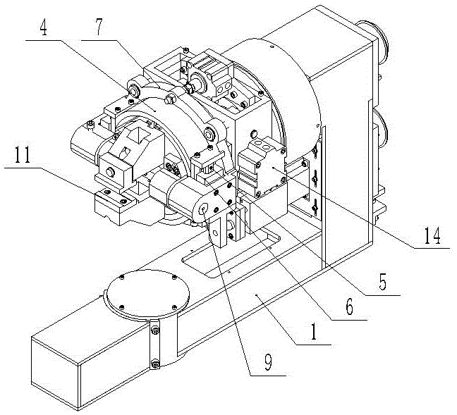
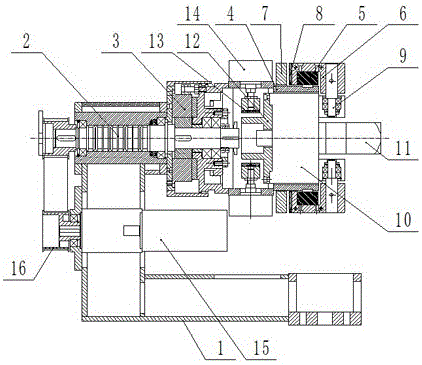
[0012] Such as figure 1 , figure 2 As shown, the workpiece clamping tracking and positioning device includes a rotary arm frame 1, a rotary air shaft 2 is arranged in the horizontal direction in the rotary arm frame 1, and a rotary electromagnetic clutch 3 and a rotary electromagnetic clutch 3 that cooperate with each other are provided at the front end of the rotary air shaft 2. The turntable 4 and the outer sides of the turntable 4 are respectively provided with translation slide rails 5, and each translation slide rail 5 is provided with a sliding seat 6, and the outside of the turntable 4 is also provided with a brake ring 7, and the brake ring 7 is formed by The driving device drives it to move axially along the outer surface of the rotary disc 4. The sliding seat 6 is provided with a brake pad 8 that ma...


PUM


Abstract

The invention relates to a tracking and positioning device for clamping of workpieces. The tracking and positioning device comprises a rotary arm rest. A rotary air shaft is arranged in the rotary arm rest. A rotary electromagnetic clutch and a rotary disc are arranged at the front end of the rotary air shaft. Horizontal moving sliding rails are arranged on the two sides of the outer portion of the rotary disc and provided with sliding seats. A braking ring is further arranged on the outer portion of the rotary disc. The sliding seats are provided with brake pads. Rotating shafts are arranged in the sliding seats. A pneumatic chuck is arranged in the rotary disc. A clamping jaw is arranged at the front end of the pneumatic chuck, and a brake seat is fixed to the rear end of the pneumatic chuck. A brake belt matched with the brake seat is arranged on the periphery of the brake seat and is driven by an air cylinder arranged on the rotary disc. The tracking and positioning device can achieve tracking adjustment in any direction, so that after the front ends of the workpieces are positioned, the rear ends of the workpieces in different shapes and of different structures are clamped and positioned, the front ends of the workpieces are maintained in the center positioning state, and thus the polishing quality of the workpieces is improved.

Description

technical field [0001] The invention relates to the technical field of polishing machines, in particular to a workpiece clamping, tracking and positioning device. Background technique [0002] After the hardware tools are made into blanks, they need to be polished. For example, for pliers, it is necessary to polish the four sides of the pliers head. At present, ordinary small processing workshops usually use manual polishing. This polishing method not only has low work efficiency, but also the workpiece is easy to fly out during polishing, causing production accidents. At present, there are automatic polishing machines specially used for polishing workpieces. This kind of polishing machine can only be used for workpieces with neat specifications and small size deviation. However, due to the limitations of current processing conditions, it is difficult to make the blanks of hardware tools neat in specifications. When these blanks are placed in an automatic polishing machine...

Claims


Application Information

Patent Timeline
Patent Type & Authority Patents(China)
IPC IPC(8): B24B41/06
CPCB24B41/06
Inventor 陈震丁惠忠陈小军
Owner ZHANGJIAGANG JUSHENG NUMERICAL CONTROL EQUIP TECH CO LTD
Learn More