Numerical control hydraulic machine

A technology of hydraulic press and pressure oil source, which is applied in the direction of stamping machines, presses, manufacturing tools, etc., can solve the problem of high tonnage, achieve the effect of simplifying the mechanical structure, simple structure, and saving external guide devices

Active Publication Date: 2015-11-18
天津正城城市基础设施投资股份有限公司
View PDF10 Cites 8 Cited by
  • Summary
  • Abstract
  • Description
  • Claims
  • Application Information

AI Technical Summary

Problems solved by technology

Most hydraulic presses for forging are hydraulic presses with high tonnage

Method used


Image

  • Numerical control hydraulic machine
  • Numerical control hydraulic machine
  • Numerical control hydraulic machine

Examples


Embodiment 1

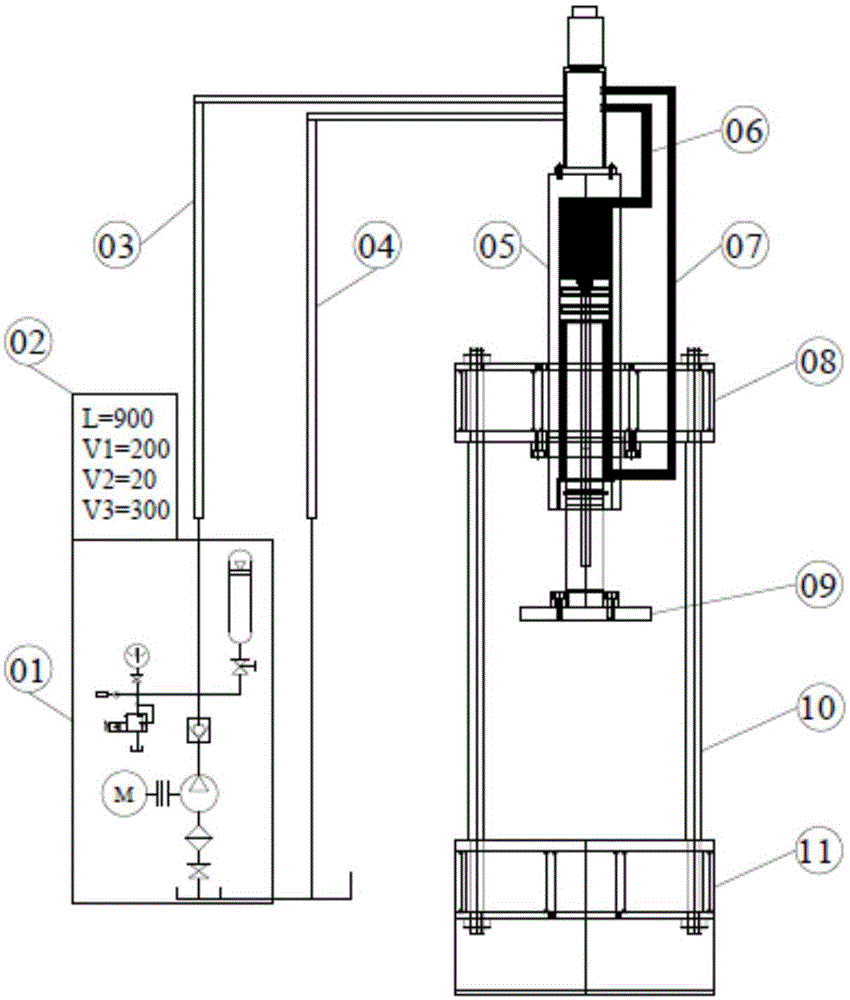
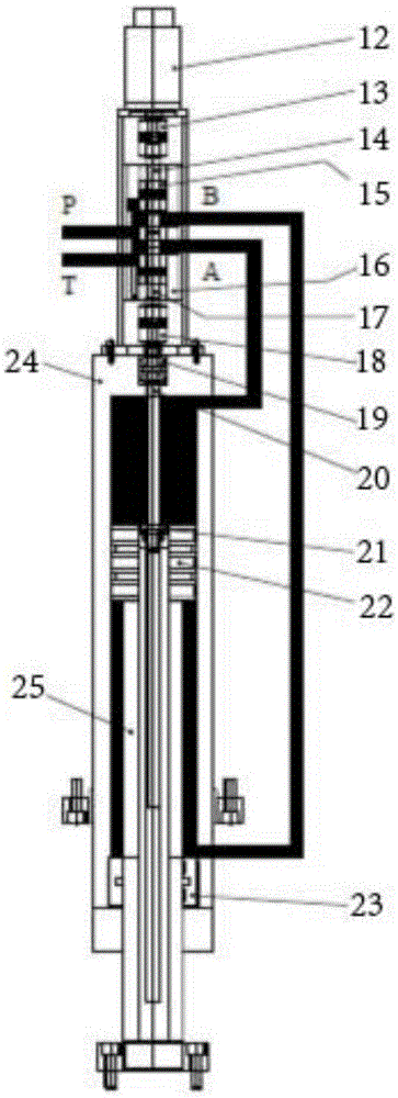
[0024] A numerically controlled hydraulic machine, including a pressure oil source 01, an operation screen 02, a high pressure oil pipe 03, an oil return pipe 04, a numerically controlled oil cylinder 05, an oil pipe in the upper chamber of the oil cylinder 06, an oil pipe in the lower chamber of the oil cylinder 07, a pressure head 09, and a mounting frame for the numerically controlled oil cylinder. The top of the source 01 is provided with an operation screen 02, and the top of the pressure oil source 01 is also provided with an oil outlet. The oil return port is connected to one end of the oil return pipe 04, and the other end of the oil return pipe 04 is connected to the numerical control oil cylinder 05. The numerical control oil cylinder 05 includes a servo motor 12, a valve body 16 and a cylinder body 24, and the servo motor 12 is set on the top of the valve body 16 , the lower end of the valve body 16 is provided with a cylinder body 24, the valve body 16 is connected ...

Embodiment 2

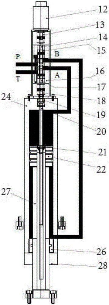
[0032] A numerically controlled hydraulic machine, including a pressure oil source 01, an operation screen 02, a high pressure oil pipe 03, an oil return pipe 04, a numerically controlled oil cylinder 05, an oil pipe in the upper chamber of the oil cylinder 06, an oil pipe in the lower chamber of the oil cylinder 07, a pressure head 09, and a mounting frame for the numerically controlled oil cylinder. The top of the source 01 is provided with an operation screen 02, and the top of the pressure oil source 01 is also provided with an oil outlet. The oil return port is connected to one end of the oil return pipe 04, and the other end of the oil return pipe 04 is connected to the numerical control oil cylinder 05. The numerical control oil cylinder 05 includes a servo motor 12, a valve body 16 and a cylinder body 24, and the servo motor 12 is set on the top of the valve body 16 , the lower end of the valve body 16 is provided with a cylinder body 24, the valve body 16 is connected ...

Embodiment 3

[0040] A numerically controlled hydraulic machine, including a pressure oil source 01, an operation screen 02, a high pressure oil pipe 03, an oil return pipe 04, a numerically controlled oil cylinder 05, an oil pipe in the upper chamber of the oil cylinder 06, an oil pipe in the lower chamber of the oil cylinder 07, a pressure head 09, and a mounting frame for the numerically controlled oil cylinder. The top of the source 01 is provided with an operation screen 02, and the top of the pressure oil source 01 is also provided with an oil outlet. The oil return port is connected to one end of the oil return pipe 04, and the other end of the oil return pipe 04 is connected to the numerical control oil cylinder 05. The numerical control oil cylinder 05 includes a servo motor 12, a valve body 16 and a cylinder body 24, and the servo motor 12 is set on the top of the valve body 16 , the lower end of the valve body 16 is provided with a cylinder body 24, the valve body 16 is connected ...


PUM


Abstract

The invention provides a numerical control hydraulic machine. An operation screen is arranged at the top end of a pressure oil source; an oil outlet is also formed in the top end of the pressure oil source and is connected with one end of a high-pressure oil pipe; the other end of the high-pressure oil pipe is connected with a numerical control oil cylinder; an oil returning opening is formed in the bottom end of the pressure oil source and is connected with one end of an oil returning pipe; the other end of the oil returning pipe is connected with the numerical control oil cylinder; a servo motor is arranged at the top end of a valve body; a cylinder body is arranged at the lower end of the valve body; the valve body is connected with the upper end of the cylinder body by an upper chamber oil pipe of the oil cylinder and is connected with the lower end of the cylinder body by a lower chamber oil pipe of the oil cylinder; a pressure head is arranged at the bottom end of the numerical control oil cylinder; the numerical control oil cylinder is arranged on a numerical control oil cylinder arranging frame. The numerical control hydraulic machine is capable of solving the synchronization problem of more than two numerical control oil cylinders; the position control precision of the pressure head is high; the velocity of movement of the pressure head is controllable; the use of a distance setting device, complex valve block and valve unit, expensive proportional valve and proportional pump and the like is avoided; a hydraulic system and an overall mechanical structure are simplified, so the reliability of the overall machine is improved.

Description

technical field [0001] The invention relates to the technical field, and more specifically, relates to a numerically controlled hydraulic machine. Background technique [0002] A hydraulic press is a machine that uses liquid as a working medium and is made according to Pascal's principle to transfer energy to realize various processes. A hydraulic press generally consists of three parts: the machine (main machine), the power system and the hydraulic control system. Hydraulic presses are classified into valve hydraulic presses, liquid hydraulic presses, and engineering hydraulic presses. [0003] A hydraulic press is a machine that uses liquid as a working medium to transfer energy to achieve various processes. In addition to being used for forging and forming, hydraulic presses can also be used for straightening, pressing, packaging, briquetting and pressing plates, etc. Hydraulic presses include hydraulic presses and oil presses. Those with water-based liquid as the worki...

Claims


Application Information

Patent Timeline
Patent Type & Authority Applications(China)
IPC IPC(8): B30B1/32B30B15/16B30B15/18B30B15/20
Inventor 赵晓波
Owner 天津正城城市基础设施投资股份有限公司
Why Eureka
Try Eureka