Electrolyzer feeding system and electrolyzer system

An electrolytic cell and material cutting technology, applied in the field of electrolysis, can solve the problems of difficulty in the dissolution process of alumina, reduction of alumina raw materials, and increased energy consumption, so as to reduce the fluctuation of the concentration of the electrolyte solution, reduce the formation of precipitates at the bottom of the tank, and improve the The effect of cutting accuracy

Active Publication Date: 2018-08-07
SNTO TECH GRP
View PDF14 Cites 0 Cited by
  • Summary
  • Abstract
  • Description
  • Claims
  • Application Information

AI Technical Summary

Problems solved by technology

[0004] First of all, interval feeding is adopted, the concentration of alumina is low before feeding and high after feeding, and the thermal balance of the tank fluctuates greatly, resulting in poor stability of the electrolytic cell and a decrease in current efficiency;
[0005] Secondly, due to the current low superheat process route, if a large amount of alumina is quickly fed in at a time by point feeding, it will make the dissolution process of alumina more difficult, and the undissolved alumina will sink into the aluminum liquid, resulting in A large amount of aluminum oxide precipitates accumulate in the aluminum liquid layer directly below the feed port, and the precipitate covers the bottom of the furnace with the flow of the aluminum liquid, causing an increase in the pressure drop at the bottom of the furnace and increasing energy consumption. In severe cases, it can lead to deformed furnace and affect the life of the tank;
[0006] Furthermore, a large amount of alumina that is fed into the alumina electrolytic cell is accelerated on the blanking slope, and scattered around after hitting the shelling head at the outlet, which will lead to a decrease in the alumina raw material that actually enters the alumina electrolytic cell, and the accuracy of blanking is poor, and The rapid loading of alumina is also easy to cause blockage at the feeding port

Method used


Image

  • Electrolyzer feeding system and electrolyzer system
  • Electrolyzer feeding system and electrolyzer system

Examples


Embodiment Construction

[0024] The following will clearly and completely describe the technical solutions in the embodiments of the present invention with reference to the accompanying drawings in the embodiments of the present invention. Obviously, the described embodiments are only some, not all, embodiments of the present invention. Based on the embodiments of the present invention, all other embodiments obtained by persons of ordinary skill in the art without making creative efforts belong to the protection scope of the present invention.

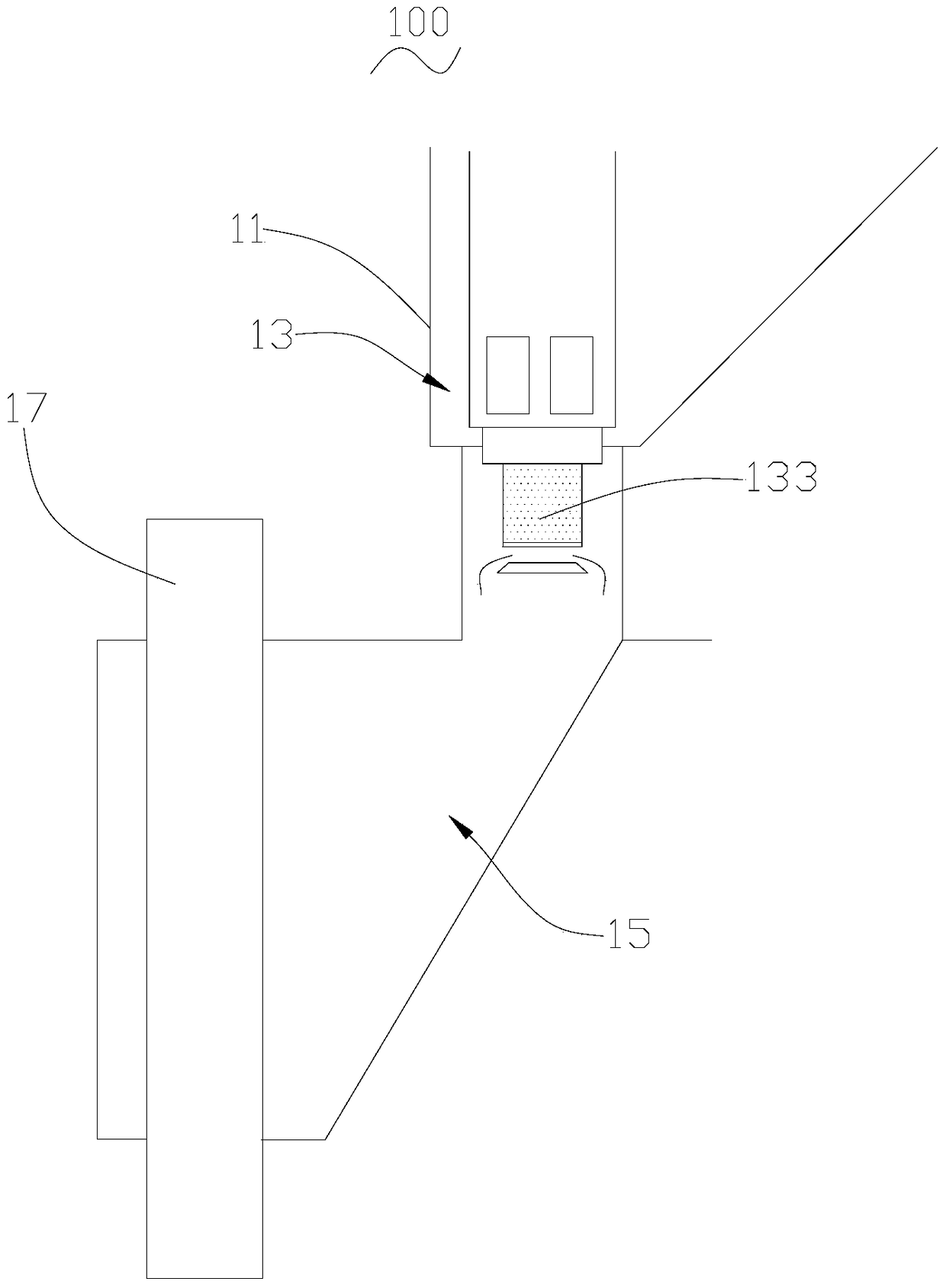
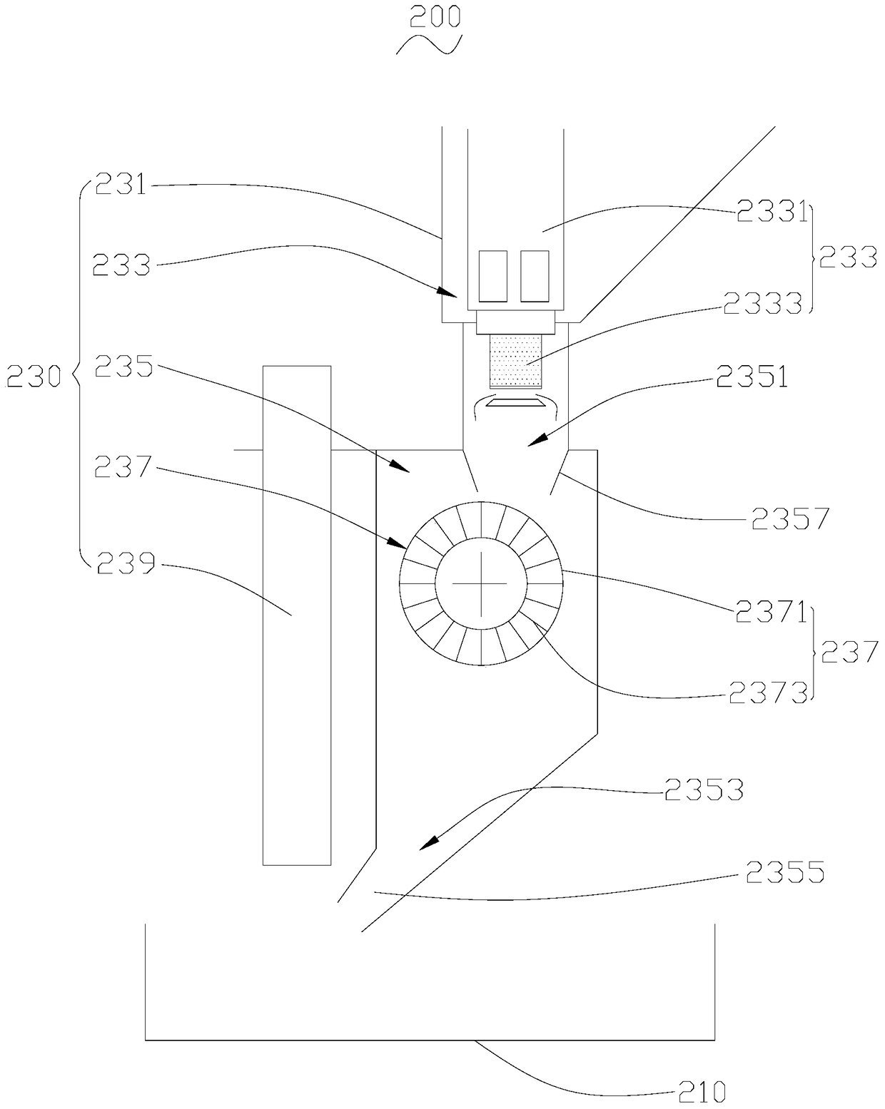
[0025] see figure 2 , is a structural schematic view of an embodiment of the electrolyzer system 200 provided by the present invention. The electrolytic cell system 200 includes an electrolytic cell 210 and an electrolytic cell feeding system 230 . The electrolytic tank feeding system 230 is arranged above the electrolytic tank 210, and feeds electrolyte raw materials (not shown in the figure) into the electrolytic tank 210. The electrolyte raw materials inc...


PUM


Abstract

The invention provides an electrolytic cell feeding system and an electrolytic cell system. The electrolytic cell feeding system comprises a material box, a constant-volume feeder and a feeding chute. The material box contains electrolyte raw materials. The constant-volume feeder is partially contained in the material box and outputs the electrolyte raw materials contained in the material box to the feeding chute. The feeding chute is arranged below the material box and comprises an upper material opening and a lower material opening. The upper material opening is located below the constant-volume feeder and receives the electrolyte raw materials provided by the constant-volume feeder. A rotary drum is arranged in the feeding chute and located between the upper material opening and the lower material opening. A groove structure is formed in the surface of the rotary drum. The electrolyte raw materials fall into the groove structure of the rotary drum through the upper material opening. The electrolytic cell system is provided with the electrolytic cell feeding system.

Description

technical field [0001] The invention relates to the technical field of electrolysis, in particular to an electrolytic tank feeding system and an electrolytic tank system using the electrolytic tank feeding system. Background technique [0002] At present, the feeding method of the electrolytic cell is usually to use a timed constant volume feeder for interval feeding. Take the point-type feeding system of alumina electrolytic cell as an example, such as figure 1 As shown, the alumina in the feed box 11 of the point-type feeding system 100 of the alumina electrolytic cell is driven into the constant container 133 of the constant-volume feeder 13, and is quantified according to the timing and interval. Put it into the hopper 15, and then enter the alumina electrolytic cell (not shown). Wherein, the shelling head 17 of the alumina electrolytic cell runs through the cutting chute 15 . In the point feeding system 100 of the alumina electrolytic cell, within a set time, a fixed...

Claims


Application Information

Patent Timeline
Patent Type & Authority Patents(China)
IPC IPC(8): C25C7/00C25C3/14
Inventor 周兴华章宣洪波敬叶灵
Owner SNTO TECH GRP
Why Eureka
Try Eureka