Aluminum electrolytic cell blanking system and aluminum electrolytic cell system

An aluminum electrolytic cell and material cutting technology, applied in the field of aluminum electrolysis, can solve the problems of increased furnace bottom pressure drop, material blockage at the feeding port, poor stability of aluminum electrolytic cell, etc. Improved material accuracy, uniform and stable dissolution

Active Publication Date: 2017-09-29
内蒙古创源金属有限公司
View PDF9 Cites 0 Cited by
  • Summary
  • Abstract
  • Description
  • Claims
  • Application Information

AI Technical Summary

Problems solved by technology

[0003] However, with intermittent blanking, the alumina concentration is low before blanking and high after blanking, and the thermal balance of the tank fluctuates greatly, resulting in poor stability of the aluminum electrolytic cell and a decrease in current efficiency; due to the current low superheat process route, if A large amount of alumina is quickly fed into the point feeding method at a time, which will make the dissolution process of alumina more difficult, and the undissolved alumina will sink into the aluminum liquid, causing a large amount of alumina to accumulate in the aluminum liquid layer directly below the feeding port Precipitation, precipitation covers the bottom of the furnace with the flow of molten aluminum, causing an increase in the pressure drop at the bottom of the furnace and increasing energy consumption. In severe cases, it can lead to deformed furnace and affect the service life of the aluminum electrolytic cell; Accelerate upward, and spread out after the outlet hits the shelling head, which will reduce the alumina raw material actually entering the aluminum electrolytic cell, and the accuracy of feeding is poor, and the rapid feeding of alumina will easily cause blockage at the feeding port
Therefore, the interval feeding system of the aluminum electrolytic cell in the related art has the disadvantages of poor stability of the aluminum electrolytic cell, low current efficiency, high energy consumption, reduced service life and poor alumina feeding effect

Method used


Image

  • Aluminum electrolytic cell blanking system and aluminum electrolytic cell system
  • Aluminum electrolytic cell blanking system and aluminum electrolytic cell system

Examples


Embodiment Construction

[0022] In order to facilitate the understanding of the present invention, the present invention will be described more fully below with reference to the associated drawings. Preferred embodiments of the invention are shown in the accompanying drawings. However, the present invention can be embodied in many different forms and is not limited to the embodiments described herein. On the contrary, these embodiments are provided to make the understanding of the disclosure of the present invention more thorough and comprehensive.

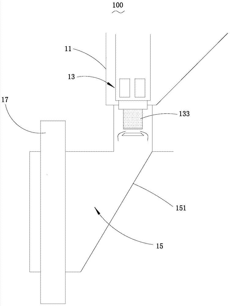
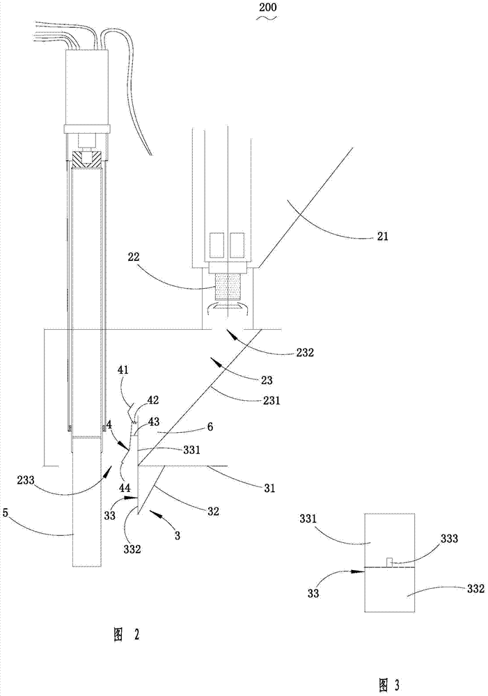
[0023] refer to figure 2 and image 3 As shown in the present application, a feeding system 200 for an aluminum electrolytic cell includes a material box 21 , a constant volume feeder 22 and a feeding tank 23 . The material box 21 accommodates the alumina raw material, and the constant-volume feeder 22 is partly accommodated in the material box 21 , and the constant-volume feeder 22 outputs the alumina material contained in the material box 21 to the ...


PUM

PropertyMeasurementUnit
areaaaaaaaaaaa

Abstract

The invention provides an aluminum electrolysis cell feeding system which comprises a material box, a constant-volume feeding device and a feeding chute. The material box contains aluminum oxide raw materials, the constant-volume feeding device is partially contained in the material box, the constant-volume feeding device outputs the aluminum oxide raw materials contained in the material box to the feeding chute, and the feeding chute is arranged below the material box and comprises a material inlet, a feeding opening and a material guide inclined wall; the material inlet is located below the constant-volume feeding device and receives the aluminum oxide raw materials provided by the constant-volume feeding device, the upper end face of the material guide inclined wall is flush with the material inlet, the lower end face of the material guide inclined wall is flush with the feeding opening, and the aluminum electrolysis cell feeding system further comprises a buffer and an automatic dredging device. Compared with the prior art, the aluminum electrolysis cell feeding system has the advantages that an aluminum electrolysis cell is good in stability, high in current efficiency, low in energy consumption, long in service life and good in aluminum oxide feeding effect.

Description

【Technical field】 [0001] The invention relates to the technical field of aluminum electrolysis, in particular to an aluminum electrolytic cell blanking system and an aluminum electrolytic cell system. 【Background technique】 [0002] The feeding method of the aluminum electrolytic cell is usually to use a timed constant volume feeder for interval feeding. like figure 1 As shown, in the interval-type feeding system 100 of the aluminum electrolytic cell of the related art, the alumina in the material box 11 is driven into the constant container 133 of the constant-volume feeder 13, and is fed at intervals in a regular and quantitative manner. The chute 15 slides into the aluminum electrolytic cell (not shown) along the inclined wall 151 of the material guide 15 of the chute 15. Wherein, the shelling head 17 of the aluminum electrolytic cell runs through the cutting chute 15 . Within the set time, a fixed amount of alumina is dropped into the aluminum electrolytic cell at a f...

Claims


Application Information

Patent Timeline
Patent Type & Authority Patents(China)
IPC IPC(8): C25C3/14C25C3/08
CPCC25C3/08C25C3/14
Inventor 章宣洪波敬叶灵李泉
Owner 内蒙古创源金属有限公司
Why Eureka
Try Eureka