A self-convection horizontal axis tidal current energy generation device

A power generation device and self-convection technology, which is applied in hydroelectric power generation, ocean energy power generation, engine components, etc., can solve the problems that the impeller angle cannot meet the high-efficiency power generation, the blade pitch mechanism is complicated, and the reliability of the unit is reduced, so as to achieve simple installation, High reliability, the effect of solving the problem of commutation

Active Publication Date: 2017-12-15
CHINA NAT OFFSHORE OIL CORP +1
View PDF5 Cites 0 Cited by
  • Summary
  • Abstract
  • Description
  • Claims
  • Application Information

AI Technical Summary

Problems solved by technology

When the flow direction of the ocean current changes, the angle of the impeller cannot meet the requirements of high-efficiency power generation without changing the direction of the turbine
Therefore, the tidal current energy generation device in the prior art is easily affected by the environment, resulting in low power generation efficiency
In order to adapt to the changing direction of the tidal current, the current tidal current power generation device adopts the pitch change method in which the blade rotates around its own axis. The problem faced during the pitch change process is that the root of the impeller blade needs to be dynamically sealed, and the pitch change mechanism of the blade is complicated. The reliability of the unit is greatly reduced

Method used


Image

  • A self-convection horizontal axis tidal current energy generation device
  • A self-convection horizontal axis tidal current energy generation device
  • A self-convection horizontal axis tidal current energy generation device

Examples


Embodiment Construction

[0011] The present invention will be described in detail below with reference to the drawings and embodiments.

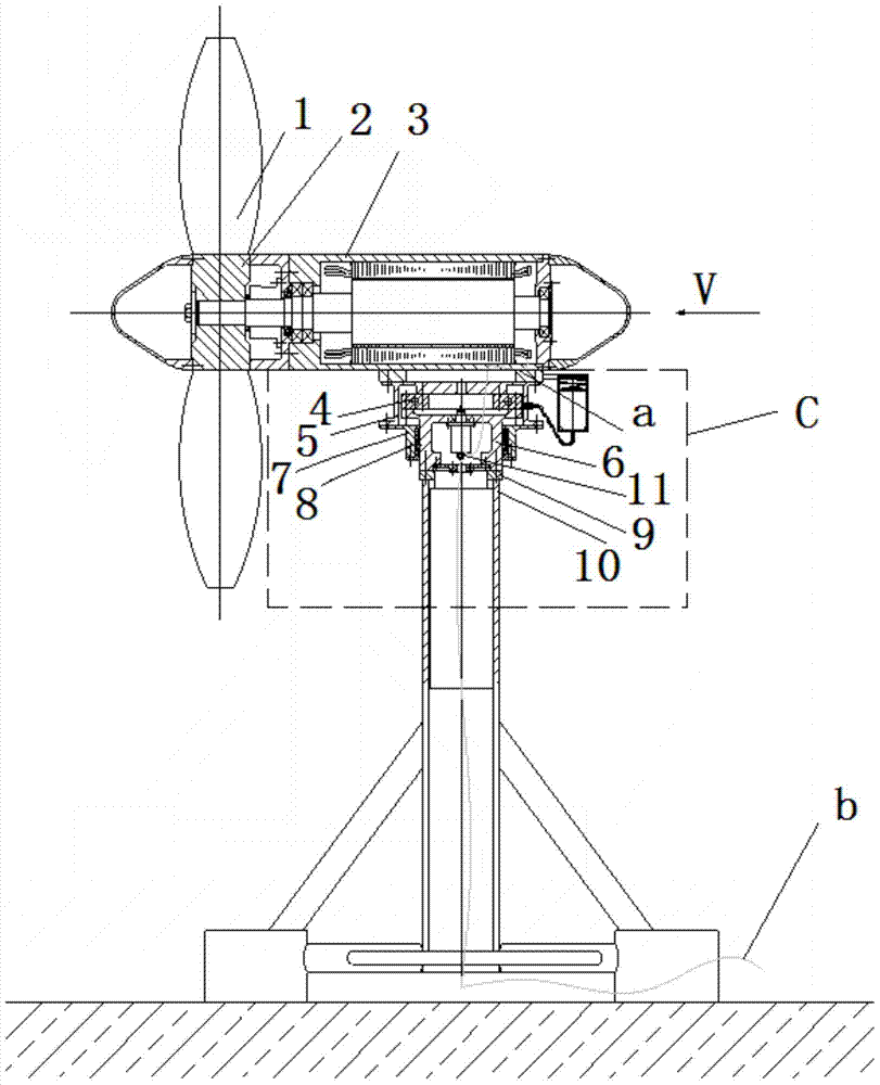
[0012] Such as figure 1 As shown, the present invention provides a self-convection type horizontal axis tidal current power generation device, which includes two parts: an impeller generator set and a self-convection device. The impeller generator set includes a blade 1, a hub 2 and a generator 3; the blade 1 is connected to the generator 3 via the hub. The blade 1 and the hub 2 are fixedly connected, and the pitch mechanism is omitted; the hub 2 and the generator 3 are directly connected through the main shaft, and the direct drive mode is adopted, and the speed increasing device is omitted. The side of the blade 1 facing the generator 3 is the oncoming surface (the current direction V is like figure 1 (Shown), the end of the generator 3 close to the blade 1 is called the front end, and the end far away from the impeller 1 is called the tail end.

[0013] Such as figur...


PUM


Abstract

The invention relates to a self-counter flow type horizontal shaft tidal current energy power generation device. The self-counter flow type horizontal shaft tidal current energy power generation device comprises an impeller generator unit and a self-counter flow device. The self-counter flow device comprises a turntable bearing, a box, a bearing end cover, a movable sealing structure, a connecting disc, a conduction slip ring, a support and a base. The impeller generator unit is directly fixed to the base through the support. The inner ring of the turntable bearing is fixedly connected with the box. The outer ring of the turntable bearing is connected with the large end face of the top of the connecting disc. One end of the box is connected with the impeller generator unit, and the other end of the box is connected with the bearing end cover. The movable sealing structure is installed in a groove of the bearing end cover. The small end face of the connecting disc is connected with the support, and the lower end of the connecting disc is fixedly connected with the base. The conduction slip ring is installed inside the connecting disc. A movable ring wire of the conduction slip ring is connected with the impeller generator unit. A fixed ring wire of the conduction slip ring penetrates the base and is connected with a shoreside bus. The self-counter flow type horizontal shaft tidal current energy power generation device can effectively solve the reversing problem of a tidal current energy power generation water turbine, high power generation efficiency is achieved, and vibration, noise and maintaining cost of the unit are effectively reduced.

Description

Technical field [0001] The invention relates to a tidal current power generation device, in particular to a self-convection type horizontal axis tidal current power generation device. Background technique [0002] Tidal energy mainly refers to the relatively stable flow in submarine waterways and straits, and the regular seawater flow caused by tides. It is the largest form of energy in ocean energy. Unlike other forms of ocean energy, tidal energy is continuous and Relatively stable, changes can be followed, and can be predicted and forecasted in advance; tidal current power generation does not block the sea to build dams, and the generator set is usually submerged in the sea, which has little impact on marine life, and does not cause three wastes pollution to the environment. In the conventional hydropower construction, the headaches of occupation of farmland and resettlement of immigrants are the most promising for commercial development. At present, countries around the worl...

Claims


Application Information

Patent Timeline
Patent Type & Authority Patents(China)
IPC IPC(8): F03B13/26F03B11/00
CPCY02E10/20Y02E10/30
Inventor 张琳孔凡凯李志川朱永伟马强张理
Owner CHINA NAT OFFSHORE OIL CORP
Why Eureka
Try Eureka