Speed regulating type hydraulic coupling

A technology of hydraulic coupling and coupling, which is applied in the direction of fluid transmission, belt/chain/gear, mechanical equipment, etc., can solve the problems of many connection points of working oil pipes, leakage of working oil, waste of energy, etc., and achieve short working time. , reduce leakage points, reduce the effect of pipeline connection

Inactive Publication Date: 2015-11-18
上海交大南洋机电科技有限公司
View PDF4 Cites 2 Cited by
  • Summary
  • Abstract
  • Description
  • Claims
  • Application Information

AI Technical Summary

Problems solved by technology

[0009] 1. The above method requires the circulating oil pump and electric heater to be in working condition all the time, resulting in unnecessary waste of energy;
[0010] 2. Due to the harsh environment and large temperature difference, there are many connection points of working oil pipes on the equipment, which may easily cause working oil leakage

Method used


Image

  • Speed regulating type hydraulic coupling
  • Speed regulating type hydraulic coupling
  • Speed regulating type hydraulic coupling

Examples


Embodiment Construction

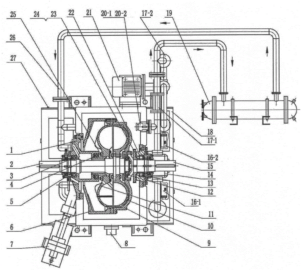
[0029] In order to make the present invention more obvious and easy to understand, a preferred embodiment is described in detail as follows in conjunction with the accompanying drawings.

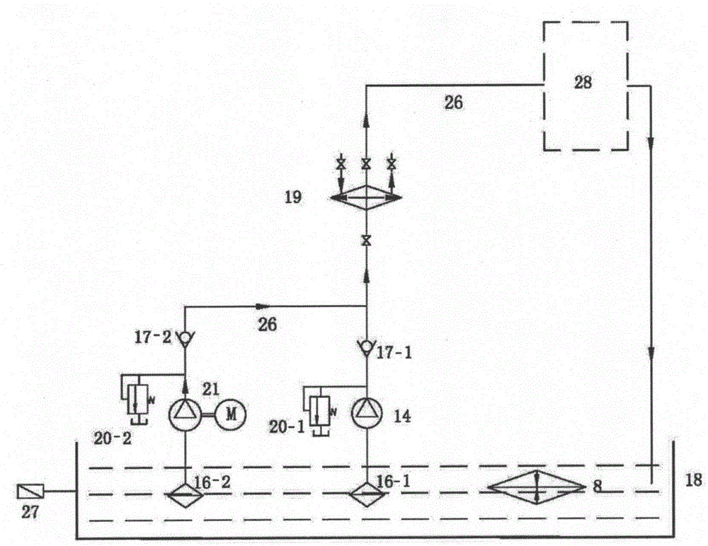
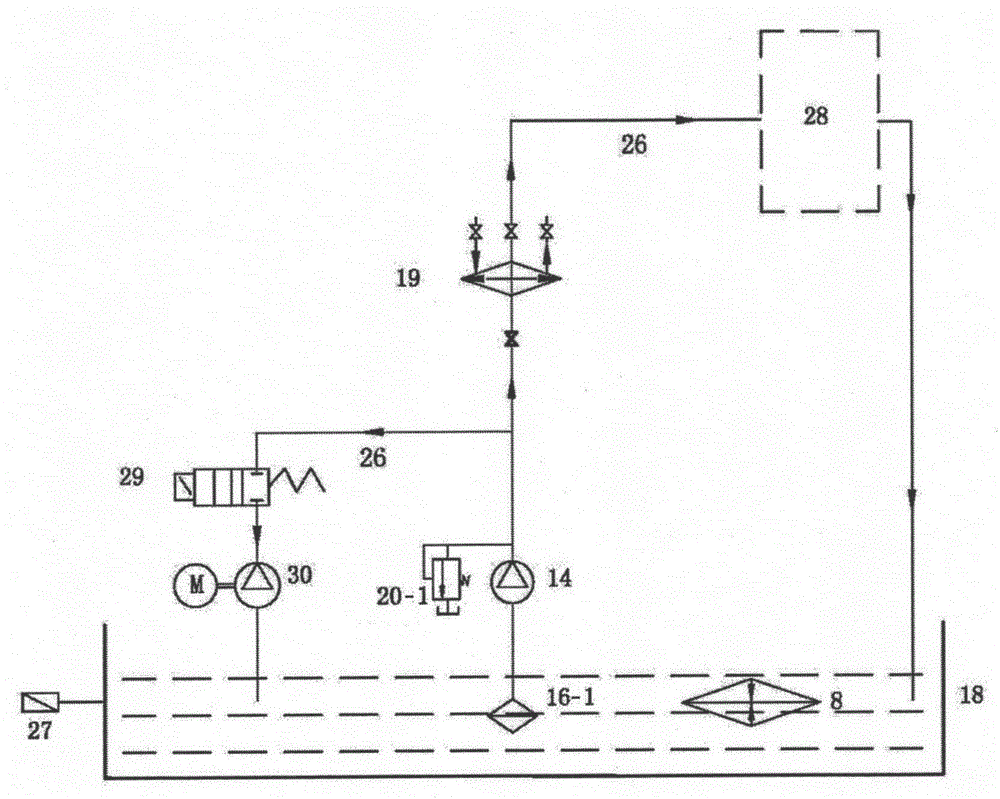
[0030] In the speed-regulating hydraulic coupling provided by the present invention, the originally configured circulating oil pump 21 is changed to an oil suction pump 30, and the second oil filter 16-2, the first check valve 17-1, and the second check valve 17- 2 and the second relief valve 20-2, add a two-position two-way electromagnetic reversing valve 29, one end of the two-position two-way electromagnetic reversing valve 29 is connected to the oil suction pump 30 through a pipeline, and the other end is connected to the cooler through a pipeline 19. Form a new speed-regulating hydraulic coupling, such as image 3 shown. Compared with the original circulating oil pump 21, the displacement of the oil suction pump 30 is reduced, and the oil flow direction is changed. The oil pump 30 suc...


PUM


Abstract

The invention provides a speed regulating type hydraulic coupling which comprises a box containing hydraulic oil. A first oil filter and an electric heater are both immersed in the hydraulic oil, and a thermal resistor is arranged on the box. The first oil filter, a working oil pump, a cooler and a coupling rotating body are sequentially connected through working oil pipes, and an outlet of the coupling rotating body is connected to a hydraulic oil cavity of the box through the working oil pipe, so that a working oil system is formed. One end of an electromagnetic directional valve is connected with the pipe between the working oil pump and the cooler, the other end of the electromagnetic directional valve is connected with a suction port of an oil suction pump, and a discharging port of the oil suction pump is connected with the hydraulic oil cavity of the box. The working oil system is used for providing the hydraulic oil needed by normal work of the coupling; when the coupling needs to stop working, the working oil pump is stopped, the electromagnetic directional valve is powered on, and the oil suction pump is started to suck residual working oil in the working oil system back into the box. The speed regulating type hydraulic coupling is convenient to control, long in service life, low in energy consumption and simple in structure, the cost is reduced, and the use performance is improved.

Description

technical field [0001] The invention relates to a speed-regulating hydraulic coupling, in particular to a speed-regulating hydraulic coupling for outdoor use. Background technique [0002] The speed-regulating hydraulic coupling is a hydraulic transmission device that transmits power with liquid as the medium. It is installed between the motor and the working machine (such as fans, water pumps, and belt conveyors). stage to adjust the speed of the working machine. [0003] The structure of the traditional speed-regulating fluid coupling is as follows: figure 1 As shown, it mainly consists of oil inlet and discharge chamber 1, turbine shaft 2, first bearing 3, second bearing 4, end cover 5, rotating casing 6, electric actuator 7, electric heater 8, back wheel 9, turbine 10 , pump wheel 11, third bearing 12, fourth bearing 13, working oil pump 14, pump wheel shaft 15, first oil filter 16-1, second oil filter 16-2, first check valve 17-1, Second check valve 17-2, case 18, co...

Claims


Application Information

Patent Timeline
Patent Type & Authority Applications(China)
IPC IPC(8): F16H41/24F16H41/00
CPCF16H41/00F16H41/24
Inventor 舒波阎德志
Owner 上海交大南洋机电科技有限公司
Why Eureka
Try Eureka